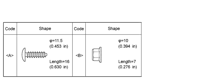
All bolts, screws and nuts relevant to installing and removing the instrument panel are shown along with an alphabetical code in the table.
LOWER INSTRUMENT PANEL > REMOVAL |
| 1. TABLE OF BOLT, SCREW AND NUT |
All bolts, screws and nuts relevant to installing and removing the instrument panel are shown along with an alphabetical code in the table.
| 2. PRECAUTION |
| 3. DISCONNECT CABLE FROM NEGATIVE BATTERY TERMINAL |
| 4. REMOVE CONSOLE BOX ASSEMBLY |
| 5. REMOVE INSTRUMENT PANEL ORNAMENT (w/ Large Ornament Panel) |
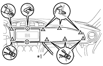 |
Using a moulding remover, disengage the 8 clips and 2 claws to remove the instrument panel ornament.
| *1 | Moulding Remover |
| 6. REMOVE CENTER INSTRUMENT CLUSTER FINISH PANEL SUB-ASSEMBLY (w/o Large Ornament Panel) |
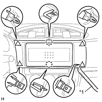 |
Using a moulding remover, disengage the 2 claws and 4 clips to remove the center instrument cluster finish panel sub-assembly.
| *1 | Moulding Remover |
| 7. REMOVE STEREO OPENING COVER WITH BRACKET (w/o Radio Receiver) |
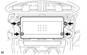 |
Remove the 4 screws to remove the stereo opening cover with bracket.
| 8. REMOVE RADIO RECEIVER ASSEMBLY WITH BRACKET (w/ Radio Receiver) |
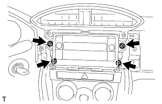 |
Remove the 4 bolts and pull the radio receiver assembly with bracket toward the rear of the vehicle.
Disconnect each connector and remove the radio receiver assembly with bracket.
| 9. REMOVE NO. 2 INSTRUMENT CLUSTER FINISH PANEL GARNISH |
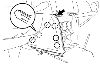 |
Remove the screw.
Disengage the 6 claws to remove the No. 2 instrument cluster finish panel garnish.
| 10. REMOVE UPPER INSTRUMENT PANEL FINISH PANEL SUB-ASSEMBLY (for LH Side) |
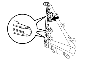 |
Remove the screw.
Disengage the 3 claws to remove the upper instrument panel finish panel sub-assembly.
| 11. REMOVE NO. 1 INSTRUMENT CLUSTER FINISH PANEL GARNISH |
| 12. REMOVE UPPER INSTRUMENT PANEL FINISH PANEL SUB-ASSEMBLY (for RH Side) |
| 13. REMOVE AIR CONDITIONING CONTROL ASSEMBLY (for Automatic Air Conditioning System) |
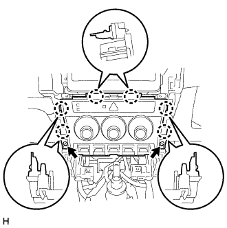 |
Remove the 2 screws.
Disengage the 6 claws.
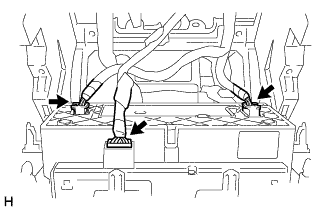 |
Disconnect each connector and remove the air conditioning control assembly.
| 14. REMOVE AIR CONDITIONING CONTROL ASSEMBLY (for Manual Air Conditioning System) |
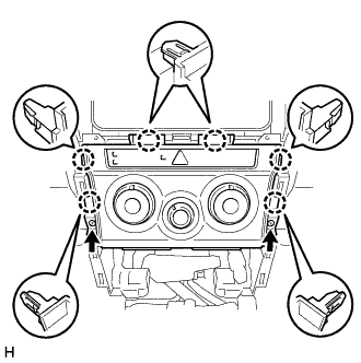 |
Remove the 2 screws and disengage the 6 claws.
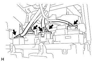 |
Disconnect each connector and air conditioning control assembly.
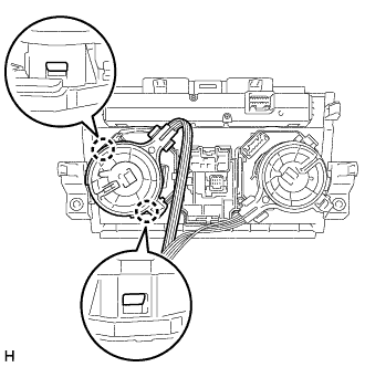 |
Disengage the 2 claws and the cable assembly (for RH side).
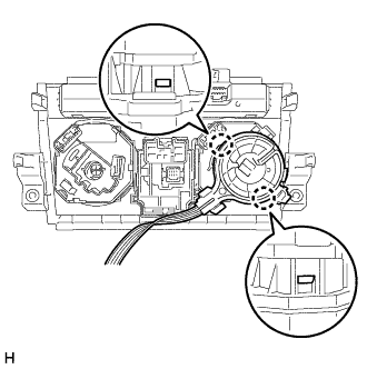 |
Disengage the 2 claws and the cable assembly (for LH side) and remove the air conditioning control assembly.
| 15. REMOVE AIR CONDITIONING CONTROL ASSEMBLY (w/o Air Conditioning System) |
| 16. REMOVE INSTRUMENT SIDE PANEL RH (w/ Airbag Cut Off Switch) |
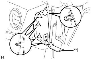 |
Using a moulding remover, disengage the claw and 4 clips.
| *1 | Moulding Remover |
Disconnect the connector and remove the instrument side panel RH.
| 17. REMOVE INSTRUMENT SIDE PANEL RH (w/o Airbag Cut Off Switch) |
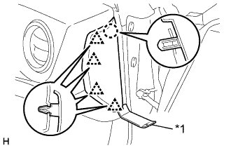 |
Using a moulding remover, disengage the claw and 4 clips and remove the instrument side panel RH.
| *1 | Moulding Remover |
| 18. REMOVE INSTRUMENT SIDE PANEL LH |
| 19. REMOVE METER HOOD SUB-ASSEMBLY |
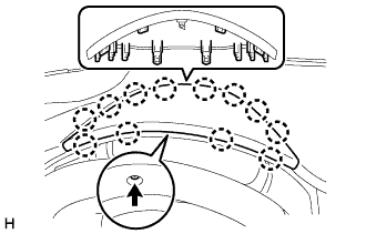 |
Remove the screw.
Disengage the 12 claws, and then pull out the meter hood sub-assembly diagonally upwards to remove it.
| 20. REMOVE UPPER INSTRUMENT PANEL METER ORNAMENT |
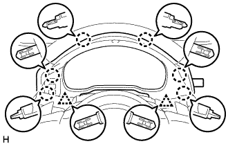 |
Disengage the 6 claws and 2 clips.
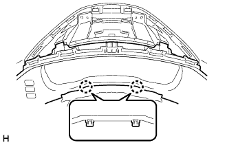 |
Disengage the 2 claws that are holding the upper instrument panel meter ornament and steering column cover together.
Disconnect the connector and remove the upper instrument panel meter ornament.
| 21. REMOVE NO. 1 INSTRUMENT PANEL UNDER COVER SUB-ASSEMBLY (w/ Knee Airbag) |
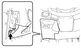 |
Remove the screw.
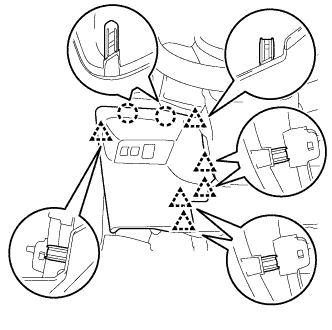 |
Disengage the 6 clips.
Disengage the 2 claws and separate the No. 1 instrument panel under cover sub-assembly.
Disconnect each connector and remove the No. 1 instrument panel under cover sub-assembly.
| 22. REMOVE NO. 2 INSTRUMENT PANEL UNDER COVER SUB-ASSEMBLY (w/ Knee Airbag) |
for LHD
Remove the screw.
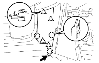 |
Disengage the 3 claws and 4 clips and remove the No. 2 instrument panel under cover sub-assembly .
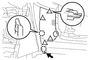 |
for RHD
Remove the screw.
Disengage the 3 claws and 4 clips.
Disconnect the cooler thermistor hose and connector and remove the No. 2 instrument panel under cover sub-assembly .
| 23. REMOVE GLOVE COMPARTMENT DOOR ASSEMBLY |
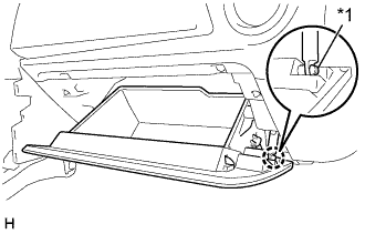 |
Disengage the claw and release the glove compartment door damper.
| *1 | Glove Compartment Door Damper |
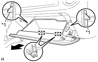 |
Release the 2 stoppers and open the glove compartment door assembly until it is horizontal.
| *1 | Stopper |
Pull the glove compartment door assembly horizontally backward to disengage the 2 hinges and remove the glove compartment door assembly.
| 24. REMOVE GLOVE COMPARTMENT DOOR DAMPER |
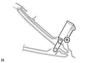 |
Disengage the claw and remove the glove compartment door damper.
| 25. REMOVE LOWER INSTRUMENT PANEL SUB-ASSEMBLY |
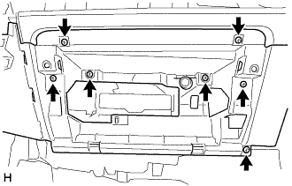 |
Remove the 7 screws.
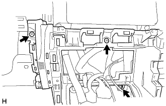 |
Remove the 2 screws and nut.
Disconnect the connectors.
Disconnect the aspirator pipe from the air conditioning unit assembly (for LHD with Automatic Air Conditioning System).
Disengage the 12 claws and clamp to remove the lower instrument panel sub-assembly.
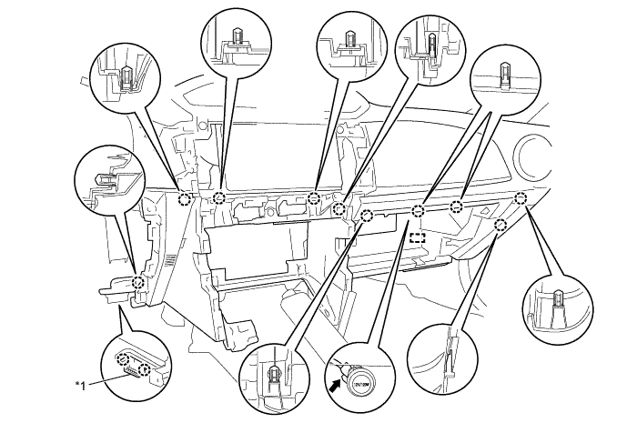
| *1 | DLC3 | - | - |