 |
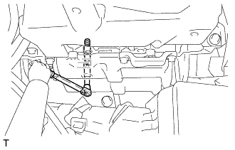
Install the 2 spark plugs onto the cylinder head sub-assembly.
- Torque:
- 17 N*m{ 173 kgf*cm , 13 ft.*lbf }
- NOTICE:
- If a component has been dropped or subjected a strong impact, replace it.
IGNITION COIL AND SPARK PLUG > INSTALLATION |
| 1. INSTALL SPARK PLUG (for Bank 1) |
|
Install the 2 spark plugs onto the cylinder head sub-assembly.
| 2. INSTALL IGNITION COIL ASSEMBLY (for Bank 1) |
Install the 2 ignition coils onto the cylinder head cover sub-assembly with the 2 bolts.
Connect the 2 ignition coil connectors to the ignition coil.
| 3. INSTALL INJECTOR DRIVER |
Install the injector driver with the 3 bolts.
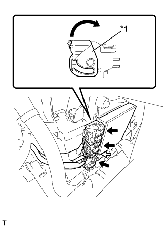 |
Connect the 4 connectors to the injector driver. Move the lock levers in the direction indicated by the arrow to lock the 3 connectors.
| *1 | Lock Lever |
 | Lock with Connector |
 | Normal Connector |
| 4. INSTALL SPARK PLUG (for Bank 2) |
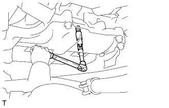 |
Install the 2 spark plugs onto the cylinder head sub-assembly.
| 5. INSTALL IGNITION COIL ASSEMBLY (for Bank 2) |
Install the 2 ignition coils onto the cylinder head cover sub-assembly with the 2 bolts.
Connect the 2 ignition coil connectors to the ignition coil.
| 6. INSTALL INJECTOR COVER (for Bank 2) |
Install the injector cover with the 2 bolts.
Engage the clamp, and install the fuel hoses.
| 7. REMOVE SST |
Hoist the engine assembly up with an engine sling device and a mini crane.
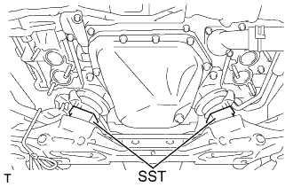 |
Remove the SST.
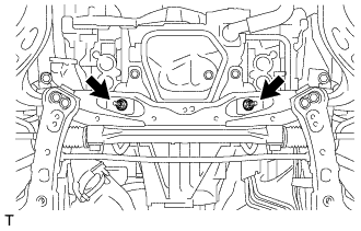 |
Install the 2 nuts.
Remove the rope that is tying the front exhaust pipe sub-assembly to the front suspension cross member sub-assembly.
| 8. REMOVE ENGINE HANGER |
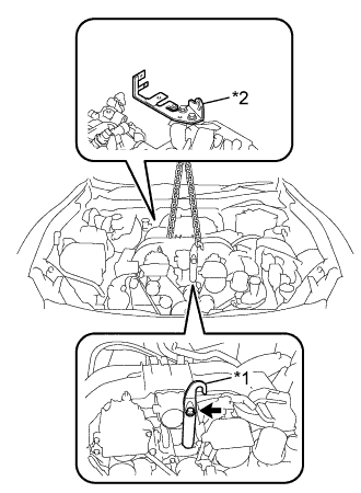 |
Install the engine hanger with the bolt, as shown in the illustration.
| *1 | No. 1 Engine Hanger |
| *2 | No. 2 Engine Hanger |
| No. 1 Engine Hanger | 12281-38030 |
| Bolt | 90119-14120 |
Use an engine sling device and a mini crane to hold the engine.
| 9. INSTALL EXHAUST MANIFOLD |
| 10. INSTALL CLUTCH FLEXIBLE HOSE BRACKET (for RHD with Manual Transmission) |
Install the clutch flexible hose bracket with the bolt.
Connect the clutch flexible tube with the clip.
| 11. CONNECT ENGINE WIRE |
Connect the engine wire with the wire harness clamp bracket mount bolt and 3 clamps.
Connect the engine wire with the 4 clamps.
| 12. INSTALL AIR CLEANER CAP WITH AIR CLEANER HOSE |
Install the air cleaner cap with air cleaner hose with the 3 blots.
Install the air cleaner cap with air cleaner hose with the 2 hose clamps.
Connect the No. 2 ventilation hose.
Connect the mass air flow meter connector.
Engage the wire harness clamp and install the wire harness to the air cleaner cap.
| 13. INSTALL FRONT SUSPENSION UPPER TO COWL BRACE SUB-ASSEMBLY LH |
Install the front suspension upper to cowl brace sub-assembly with the new bolt and 3 new nuts.
| 14. INSTALL FRONT SUSPENSION UPPER TO COWL BRACE SUB-ASSEMBLY RH |
| 15. CONNECT CABLE TO NEGATIVE BATTERY TERMINAL |