 |
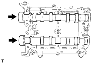
Set the intake camshaft LH and the exhaust camshaft LH to the camshaft housing sub-assembly LH.
CAMSHAFT > INSTALLATION |
| 1. INSTALL CAMSHAFT LH (for Bank 2) |
Apply engine oil to the journals of the camshaft housing sub-assembly LH.
|
Set the intake camshaft LH and the exhaust camshaft LH to the camshaft housing sub-assembly LH.
| 2. INSTALL CAMSHAFT CAP (for Bank 2) |
Using a sealer gun, apply seal packing to the contact surface of the front camshaft cap LH, intake rear camshaft cap LH and exhaust rear camshaft cap LH as shown in the illustration.
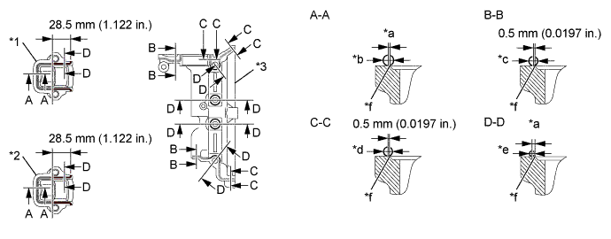
| *1 | Intake Rear Camshaft Cap LH | *2 | Exhaust Rear Camshaft Cap LH |
| *3 | Front Camshaft Cap LH | - | - |
| *a | Within 1.0 mm (0.0394 in.) | *b | φ3.0 to 4.0 mm (0.1181 to 0.1575 in.) |
| *c | φ2.5 to 3.5 mm (0.0984 to 0.1378 in.) | *d | φ2.5 to 4.0 mm (0.0984 to 0.1575 in.) |
| *e | φ1.5 to 2.5 mm (0.0591 to 0.0984 in.) | *f | Chamfer edge |
Apply engine oil to the journals of the camshaft caps, and place them on the camshaft housing sub-assembly LH.
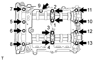 |
Tighten the 13 bolts in the order shown in the illustration to install the front camshaft cap LH, intake center camshaft cap LH, intake rear camshaft cap LH, exhaust center camshaft cap LH and exhaust rear camshaft cap LH.
| 3. INSTALL CAMSHAFT RH (for Bank 1) |
Apply engine oil to the journals of the camshaft housing sub-assembly RH.
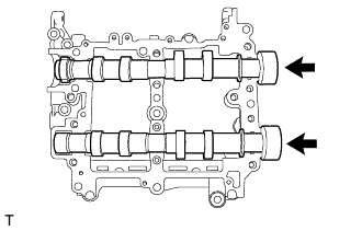 |
Set the intake camshaft RH and the exhaust camshaft RH to the camshaft housing sub-assembly RH.
| 4. INSTALL CAMSHAFT CAP (for Bank 1) |
Using a sealer gun, apply seal packing to the contact surface of the front camshaft cap RH, intake rear camshaft cap RH and exhaust rear camshaft cap RH as shown in the illustration.
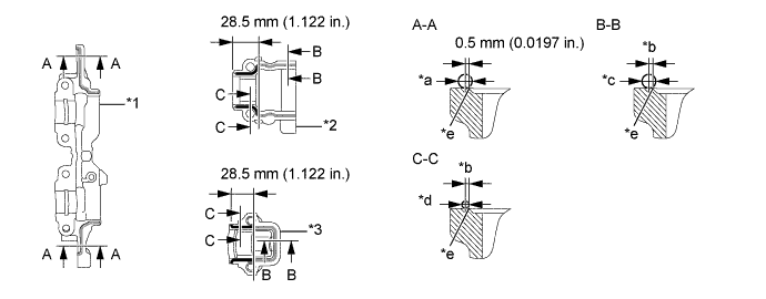
| *1 | Front Camshaft Cap RH | *2 | Intake Rear Camshaft Cap RH |
| *3 | Exhaust Rear Camshaft Cap RH | - | - |
| a | φ2.5 to 4.0 mm (0.0984 to 0.1575 in.) | b | Within 1.0 mm (0.0394 in.) |
| c | φ3.0 to 4.0 mm (0.1181 to 0.1575 in.) | d | φ1.5 to 2.5 mm (0.0591 to 0.0984 in.) |
| e | Chamfer edge | - | - |
Apply engine oil to the journals of the camshaft caps, and place them on the camshaft housing sub-assembly RH.
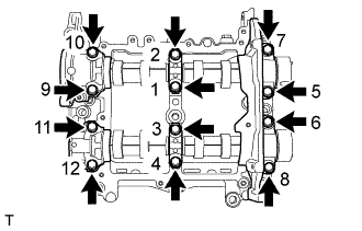 |
Tighten the 12 bolts in the order shown in the illustration to install the front camshaft cap RH, intake center camshaft cap RH, intake rear camshaft cap RH, exhaust center camshaft cap RH and exhaust rear camshaft cap RH.
| 5. INSTALL CAMSHAFT HOUSING SUB-ASSEMBLY LH |
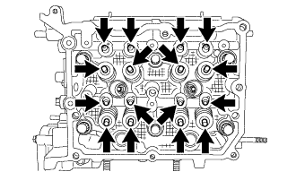 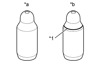 |
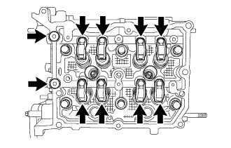
Apply engine oil to the 8 valve adjusting shims and 8 roller rocker arm pivots, and then install them to the cylinder head sub-assembly LH.
| *1 | Identification Groove |
| *a | for Bank 1 |
| *b | for Bank 2 |
 |
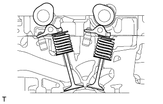
Apply engine oil to 2 new O-rings and the 8 No. 1 valve rocker arm sub-assemblies, and then install them to the cylinder head sub-assembly LH.
Using a sealer gun, apply seal packing in a continuous line as shown in the illustration.
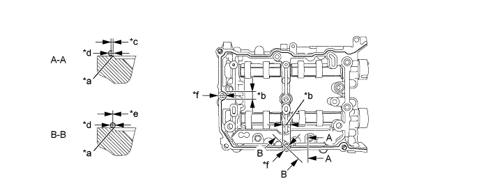
| *a | Chamfer edge | *b | Range of B-B |
| *c | within 1.0 mm (0.0394 in.) | *d | φ2.5 to 3.5 mm (0.098 to 0.138 in.) |
| *e | -0.5 to 0.5 mm (-0.0197 to 0.0197 in.) | *f | 18.0 mm (0.709 in.) |
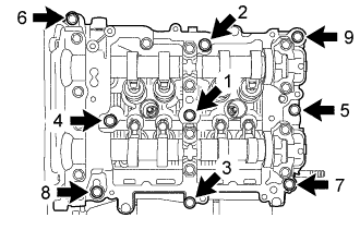 |
Tighten the 9 bolts in the order shown in the illustration to install the camshaft housing sub-assembly LH.
 |
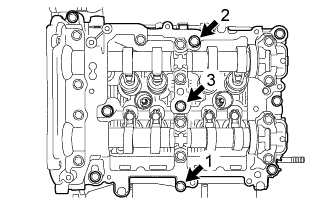 |
Loosen the 3 bolts by 180° in the order shown in the illustration.
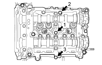 |
Tighten the 3 bolts in the order shown in the illustration.
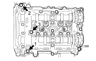 |
Loosen the 3 bolts by 180° in the order shown in the illustration.
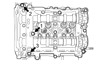 |
Tighten the 3 bolts in the order shown in the illustration.
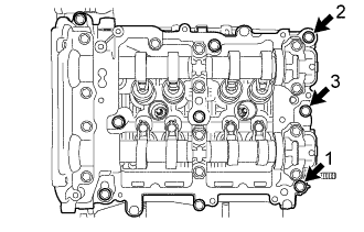 |
Loosen the 3 bolts by 180° in the order shown in the illustration.
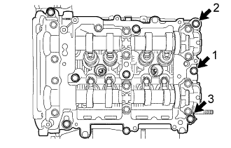 |
Tighten the 3 bolts in the order shown in the illustration.
| 6. INSTALL CYLINDER HEAD COVER SUB-ASSEMBLY LH |
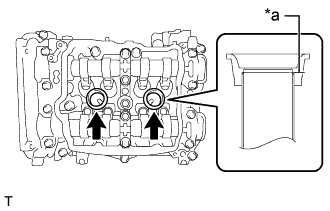 |
Apply a light layer of engine oil to 2 new spark plug tube gaskets and install them to the spark plug tubes as shown in the illustration.
| *a | Spark plug tube edge |
Install a new cylinder head cover gasket to the cylinder head cover sub-assembly LH.
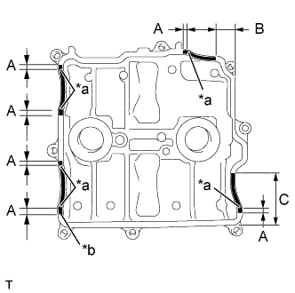 |
Using a sealer gun, apply seal packing to the mating surface of cylinder head cover sub-assembly LH as shown in the illustration.
| Area | Application Length |
| A | 10.0 mm (0.394 in.) or more |
| B | 18.8 mm (0.740 in.) or more |
| C | 63.0 mm (2.480 in.) or more |
| *a | Arch starting point |
| *b | φ2,0 to 4.0 mm (0.079 to 0.158 in.) |
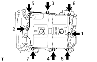 |
Tighten the 8 bolts in the order shown in the illustration and install the cylinder head cover sub-assembly LH.
| 7. INSTALL CAMSHAFT HOUSING SUB-ASSEMBLY RH |
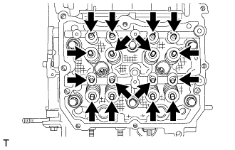 |
Apply engine oil to the 8 valve adjusting shims and 8 roller rocker arm pivots, and then install them to the cylinder head sub-assembly.
| *1 | Identification Groove |
| *a | for Bank 1 |
| *b | for Bank 2 |
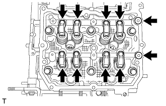 |
Apply engine oil to 2 new O-rings and the 8 No. 1 valve rocker arm sub-assemblies, and then install them to the cylinder head sub-assembly.
Using a sealer gun, apply seal packing in a continuous line as shown in the illustration.
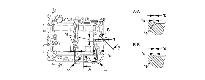
| *a | Range of B-B | *b | 0 to 1.0 mm (0 to 0.0394 in.) |
| *c | φ2.5 to 3.5 mm (0.098 to 0.138 in.) | *d | -0.5 to 0.5 mm (-0.0197 to 0.0197 in.) |
| *e | Chamfer edge | *f | 18.0 mm (0.709 in.) |
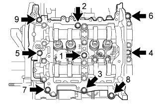 |
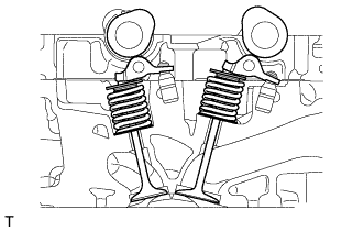
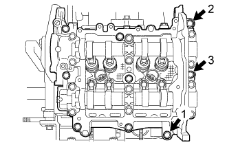
Tighten the 9 bolts in the order shown in the illustration to install the camshaft housing sub-assembly RH.
 |
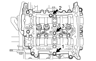 |
Loosen the 3 bolts by 180° in the order shown in the illustration.
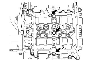 |
Tighten the 3 bolts in the order shown in the illustration.
 |
Loosen the 3 bolts by 180° in the order shown in the illustration.
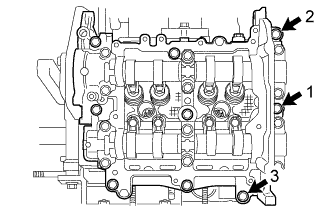 |
Tighten the 3 bolts in the order shown in the illustration.
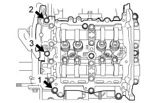 |
Loosen the 3 bolts by 180° in the order shown in the illustration.
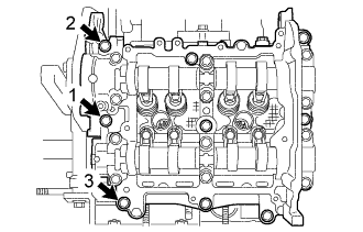 |
Tighten the 3 bolts in the order shown in the illustration.
| 8. INSTALL CYLINDER HEAD COVER SUB-ASSEMBLY RH |
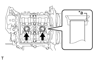 |
Apply a light layer of engine oil to 2 new spark plug tube gaskets and install them to the spark plug tubes as shown in the illustration.
| *a | Spark plug tube edge |
Install a new cylinder head cover gasket to the cylinder head cover sub-assembly RH.
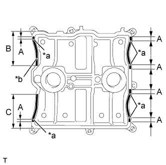 |
Using a sealer gun, apply seal packing to the mating surface of cylinder head cover sub-assembly RH as shown in the illustration.
| Area | Application Length |
| A | 10.0 mm (0.394 in.) or more |
| B | 68.0 mm (2.677 in.) or more |
| C | 70.7 mm (2.784 in.) or more |
| *a | Arch starting point |
| *b | φ2,0 to 4.0 mm (0.079 to 0.158 in.) |
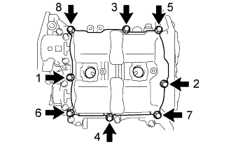 |
Tighten the 8 bolts in the order shown in the illustration and install the cylinder head cover sub-assembly RH.
| 9. INSTALL INJECTOR DRIVER BRACKET |
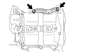 |
Install the injector driver bracket with the 2 bolts.
| 10. INSTALL SPARK PLUG (for Bank 1) |
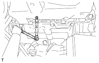 |
Install the 2 spark plugs onto the cylinder head sub-assembly.
| 11. INSTALL IGNITION COIL ASSEMBLY (for Bank 1) |
Install the 2 ignition coils onto the cylinder head cover sub-assembly with the 2 bolts.
Connect the 2 ignition coil connectors to the ignition coil.
| 12. INSTALL SPARK PLUG (for Bank 2) |
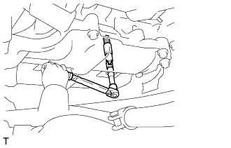 |
Install the 2 spark plugs onto the cylinder head sub-assembly.
| 13. INSTALL IGNITION COIL ASSEMBLY (for Bank 2) |
Install the 2 ignition coils onto the cylinder head cover sub-assembly with the 2 bolts.
Connect the 2 ignition coil connectors to the ignition coil.
| 14. INSTALL CAMSHAFT TIMING EXHAUST GEAR ASSEMBLY LH |
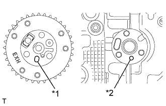 |
Install the camshaft timing exhaust gear assembly LH while aligning the knock hole of the camshaft timing exhaust gear assembly LH with the knock pin of the exhaust camshaft LH.
| *1 | Knock Hole |
| *2 | Knock Pin |
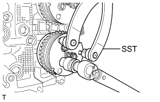 |
Using SST, hold the camshaft timing exhaust gear assembly LH, and tighten the 3 bolts with a socket "TORX" wrench E16.
| 15. INSTALL CAMSHAFT TIMING INTAKE GEAR ASSEMBLY LH |
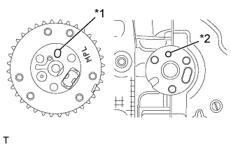 |
Install the camshaft timing exhaust gear assembly LH while aligning the knock hole of the camshaft timing intake gear assembly LH with the knock pin of the intake camshaft LH.
| *1 | Knock Hole |
| *2 | Knock Pin |
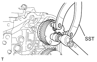 |
Using SST, hold the camshaft timing intake gear assembly LH, and tighten the 3 bolts with a socket "TORX" wrench E16.
| 16. INSTALL CAMSHAFT TIMING EXHAUST GEAR ASSEMBLY RH |
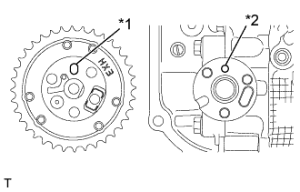 |
Install the camshaft timing intake gear assembly RH while aligning the knock hole of the camshaft timing exhaust gear assembly RH with the knock pin of the exhaust camshaft RH.
| *1 | Knock Hole |
| *2 | Knock Pin |
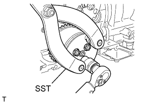 |
Using SST, hold the camshaft timing exhaust gear assembly RH, and tighten the 3 bolts with a socket "TORX" wrench E16.
| 17. INSTALL CAMSHAFT TIMING INTAKE GEAR ASSEMBLY RH |
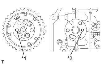 |
Install the camshaft timing intake gear assembly RH while aligning the knock hole of the camshaft timing intake gear assembly RH with the knock pin of the intake camshaft RH.
| *1 | Knock Hole |
| *2 | Knock Pin |
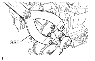 |
Using SST, hold the camshaft timing intake gear assembly RH, and tighten the 3 bolts with a socket "TORX" wrench E16.
| 18. INSTALL CRANKSHAFT TIMING GEAR OR SPROCKET |
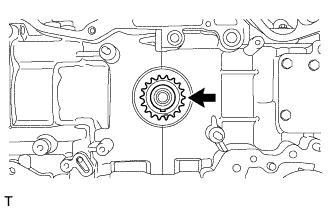 |
Install the crankshaft timing gear or sprocket.
| 19. INSTALL CHAIN SUB-ASSEMBLY (for Bank 2) |
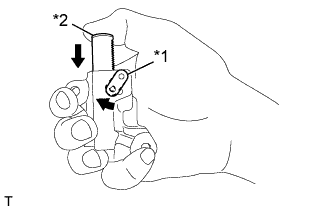 |
Move the link plate in the direction of the arrow in the illustration to press in the plunger.
| *1 | Link Plate |
| *2 | Plunger |
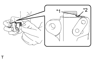 |
Insert an approximately 1 mm (0.0394 in.) diameter wire or the like into the chain tensioner assembly through the stopper pin hole, and hold the plunger.
| *1 | First notch of the plunger rack |
| *2 | Stopper Tooth |
Temporarily install the crankshaft pulley spacer and crankshaft pulley.
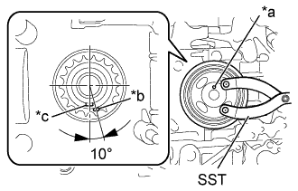 |
Using SST, set the crankshaft pulley pin hole at the position shown in the illustration.
| *a | Crankshaft Pulley Pin Hole |
| *b | Alignment Mark |
| *c | Crankshaft Timing Gear key |
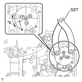 |
Using SST, turn the camshaft timing intake gear assembly LH and align the alignment mark as shown in the illustration.
| *a | Alignment Mark |
| *b | 25°to 30° |
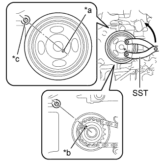 |
Using SST, turn the crankshaft about 200 degrees counterclockwise until the crankshaft pulley pin hole is aligned at the position shown in the illustration.
| *a | Crankshaft Pulley Pin Hole |
| *b | Crankshaft Timing Gear key |
| *c | Cylinder Block Guide Pin |
Remove the crankshaft pulley and crankshaft pulley spacer.
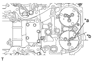 |
Align the alignment mark on the camshaft timing exhaust gear assembly LH as shown in the illustration.
| *a | Alignment Mark |
| *b | 25° to 30° |
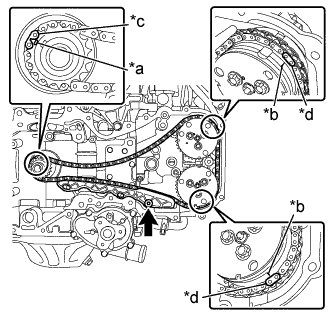 |
Install the chain sub-assembly in the following order.
| *a | Alignment Mark (Oval) |
| *b | Alignment Mark (Engraved Line) |
| *c | Mark plate (Grayish Blue) |
| *d | Mark plate (Pink) |
Align the mark plate (grayish blue) on the chain sub-assembly with the alignment mark (oval) on the crankshaft timing gear or sprocket.
Align the mark plate (pink) on the chain sub-assembly with the alignment mark (engraved line) on the camshaft timing exhaust gear assembly LH.
Align the mark plate (pink) on the chain sub-assembly with the alignment mark (engraved line) on the camshaft timing intake gear assembly LH.
Using a 5 mm hexagon socket wrench, install the No. 1 chain vibration damper with the bolt.
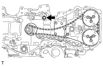 |
Install a new O-ring to the cylinder block (for bank 2).
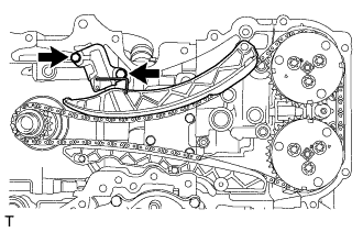 |
Install the chain tensioner slipper.
Install the No. 2 chain tensioner assembly with the 2 bolts.
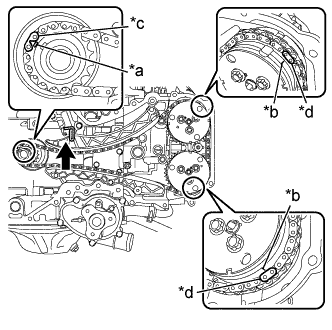 |
Check that the chain is correctly installed.
| *a | Alignment Mark (Oval) |
| *b | Alignment Mark (Engraved Line) |
| *c | Mark plate (Grayish Blue) |
| *d | Mark plate (Pink) |
The mark plate (grayish blue) on the chain sub-assembly is aligned with the alignment mark (oval) on the crankshaft timing gear or sprocket.
The mark plate (pink) on the chain sub-assembly is aligned with the alignment mark (engraved line) on the camshaft timing intake gear assembly LH.
The mark plate (pink) on the chain sub-assembly is aligned with the alignment mark (engraved line) on the camshaft timing exhaust gear assembly LH.
Pull out the wire or the like from the No. 2 chain tensioner assembly.
Temporarily install the crankshaft pulley spacer and crankshaft pulley.
Using SST, turn the crankshaft clockwise to make sure that there are no abnormal conditions.
| 20. INSTALL CHAIN SUB-ASSEMBLY (for Bank 1) |
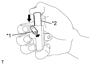 |
Move the link plate in the direction of the arrow in the illustration to press in the plunger.
| *1 | Link Plate |
| *2 | Plunger |
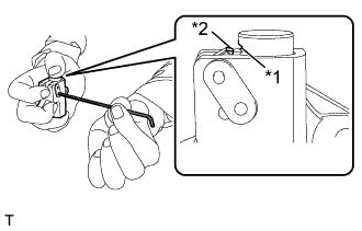 |
Insert a 2.5 mm (0.098 in.) hexagon wrench into the No. 1 chain tensioner assembly through the stopper pin hole, and hold the plunger.
| *1 | First notch of the plunger rack |
| *2 | Stopper Tooth |
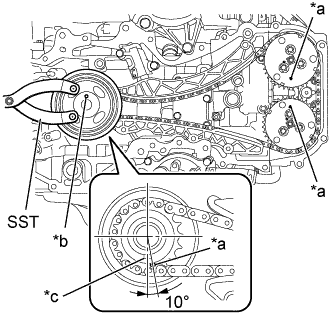 |
Using SST, turn the crankshaft pulley clockwise until the alignment marks on the camshaft timing intake gear assembly LH and the camshaft timing exhaust gear assembly LH, and the crankshaft pulley pin hole are aligned at the positions shown in the illustration.
| *a | Alignment Mark |
| *b | Crankshaft Pulley Pin Hole |
| *c | Crankshaft Timing Gear Key |
Remove the crankshaft pulley and crankshaft pulley spacer.
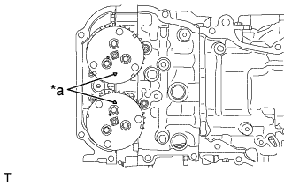 |
Align the alignment marks of the camshaft timing intake gear assembly RH and camshaft timing exhaust gear assembly RH as shown in the illustration.
| *a | Alignment Mark |
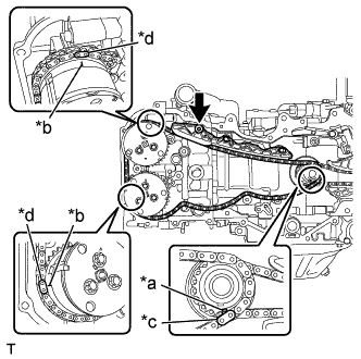 |
Install the chain sub-assembly in the following order.
| *a | Alignment Mark (Oval) |
| *b | Alignment Mark (Engraved Line) |
| *c | Mark plate (Grayish Blue) |
| *d | Mark plate (Pink) |
Align the mark plate (grayish blue) on the chain sub-assembly with the alignment mark (oval) on the crankshaft timing gear or sprocket.
Align the mark plate (pink) on the chain sub-assembly with the alignment mark (engraved line) on the camshaft timing intake gear assembly RH.
Align the mark plate (pink) on the chain sub-assembly with the alignment mark (engraved line) on the camshaft timing exhaust gear assembly RH.
Apply engine oil to the bolt.
Using a 5 mm hexagon socket wrench, install the No. 1 chain vibration damper with the bolt.
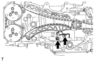 |
Install the chain tensioner slipper.
Install the No. 1 chain tensioner assembly with the 2 bolts.
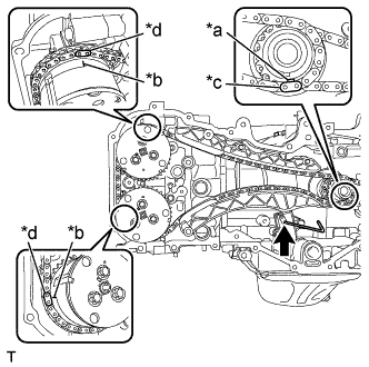 |
Check that the chain is correctly installed.
| *a | Alignment Mark (Oval) |
| *b | Alignment Mark (Engraved Line) |
| *c | Mark plate (Grayish Blue) |
| *d | Mark plate (Pink) |
The mark plate (grayish blue) on the chain sub-assembly is aligned with the alignment mark (oval) on the crankshaft timing gear or sprocket.
The mark plate (pink) on the chain sub-assembly is aligned with the alignment mark (engraved line) on the camshaft timing intake gear assembly RH.
The mark plate (pink) on the chain sub-assembly is aligned with the alignment mark (engraved line) on the camshaft timing exhaust gear assembly RH.
Pull out the hexagon wrench from the No. 1 chain tensioner assembly.
Temporarily install the crankshaft pulley spacer and crankshaft pulley.
Using SST, turn the crankshaft clockwise to make sure that there are no abnormal conditions.
Remove the crankshaft pulley and crankshaft pulley spacer.
| 21. INSTALL TIMING CHAIN OR BELT COVER SUB-ASSEMBLY |
Apply a light coat of engine oil to the 4 O-rings.
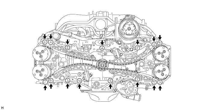
Remove any old packing material remaining on the sealing surfaces before applying seal packing.
If there are gaps at positions shown in the illustration, fill up with seal packing by using a sealer gun.
Using a sealer gun, apply seal packing in a continuous line to the timing chain cover as shown in the following illustration.
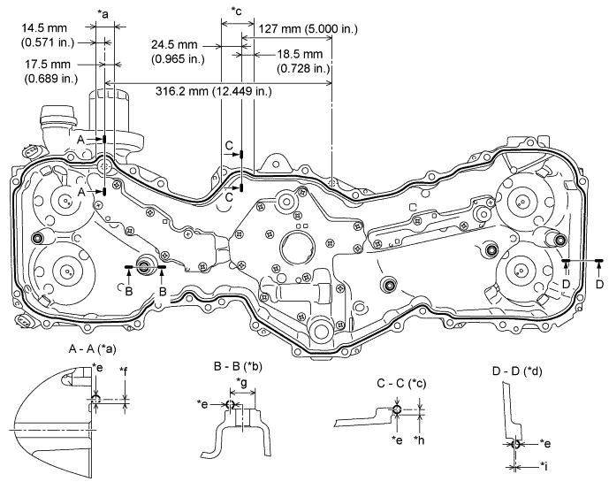
| *a | Range A | *b | Boss (5 locations) |
| *c | Range B | *d | Other than ranges A and B |
| *e | φ3.5 to 4.5 mm (0.138 to 0.177 in.) | *f | 2 mm (0.079 in.) |
| *g | φ12 mm (0.472 in.) | *h | 2.5 mm (0.098 in.) |
| *i | 0.5 mm (0.020 in.) | - | - |
Temporarily tighten the timing chain cover with the 32 bolts.
Fully tighten the 32 bolts shown in the illustration.
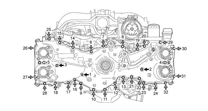
 | Bolt A |  | Bolt B |
 | Bolt C |  | Bolt D |
| Item | Length | Item | Length |
| Bolt A | 20 mm (0.787 in.) | Bolt B | 50 mm (1.969 in.) |
| Bolt C | 25 mm (0.984 in.) | Bolt D | 60 mm (2.362 in.) |
| 22. CONNECT ENGINE WIRE |
Connect the camshaft position sensor connector and camshaft timing oil control valve connector.
Engage the wire harness clamp.
Connect the engine oil pressure switch connector and engine oil temperature sensor connector.
Connect the camshaft position sensor connector and camshaft timing oil control valve connector.
Connect the 2 camshaft position sensor connectors and camshaft timing oil control valve connector.
Connect the camshaft position sensor connector.
Install the wire harness bracket with the bolt.
Engage the wire harness clamp.
Install the 2 wire harness brackets with the 2 bolts.
| 23. INSTALL TIMING CHAIN OR BELT COVER OIL SEAL |
Apply engine oil to the lip of a new timing chain or belt cover oil seal.
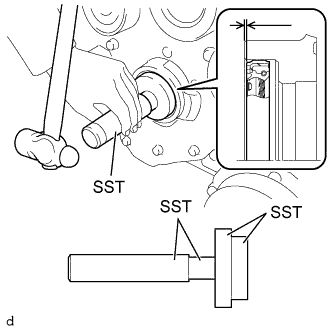 |
Using SST and a hammer, tap in the timing chain or belt cover oil seal until its surface is flush with the timing chain cover edge.
| 24. INSTALL CRANKSHAFT PULLEY |
Install the crankshaft pulley spacer.
Install a new O-ring to the crankshaft pulley spacer.
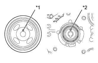 |
Install the crankshaft pulley while aligning the knock hole of the pulley with the knock pin on the crankshaft pulley spacer.
| *1 | Knock Hole |
| *2 | Knock Pin |
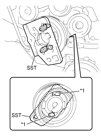 |
Install SST to the crankshaft pulley.
| *1 | Claw |
Apply engine oil to the crankshaft pulley set bolt.
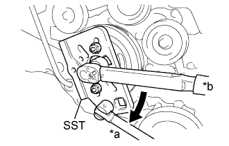 |
Using SST, hold the crankshaft pulley and tighten the crankshaft pulley set bolt.
| *a | Hold |
| *b | Turn |
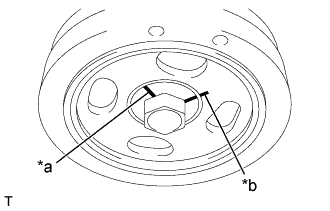 |
Using a marker, draw the reference line (A) on the crankshaft pulley set bolt and also the reference line (B) on the crankshaft pulley according to the line engraved around the crankshaft pulley set bolt head as shown in the illustration.
| *a | Reference Line A |
| *b | Reference Line B |
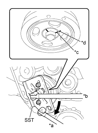 |
Using SST, hold the crankshaft pulley, and tighten the crankshaft pulley set bolt by 90° until the reference lines A and B are aligned.
| *a | Hold |
| *b | Turn |
| *c | Reference Line A |
| *d | Reference Line B |
| 25. INSTALL NO. 1 WATER BY-PASS PIPE (for Manual Transmission) |
Install the No. 1 water by-pass pipe with the 2 bolts.
Connect the water by-pass hose with the hose clamp.
| 26. INSTALL NO. 1 WATER BY-PASS PIPE (for Automatic Transmission) |
Install the No. 1 water by-pass pipe with the 2 bolts.
Connect the 2 water by-pass hoses with the 2 hose clamps.
| 27. INSTALL REAR CYLINDER HEAD PLATE (for Manual Transmission) |
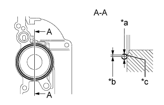 |
Using a sealer gun, apply seal packing in a continuous line as shown in the illustration.
| *a | φ2,0 to 4.0 mm (0.079 to 0.158 in.) |
| *b | Within 1.0 mm (0.0394 in.) |
| *c | Chamfer edge |
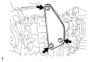 |
Install the rear cylinder head plate with the 3 bolts.
| 28. INSTALL VACUUM PUMP ASSEMBLY (for Automatic Transmission) |
Coat a new O-ring with engine oil, and install it.
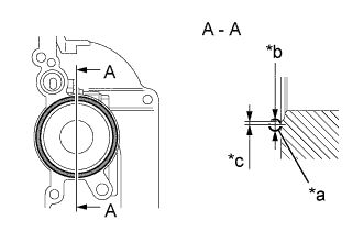 |
Apply seal packing in a continuous line as shown in the illustration.
| *a | Edge of Groove |
| *b | 2.0 to 4.0 mm (0.078 to 0.158 in.) in Diameter |
| *c | 1.0mm or Less |
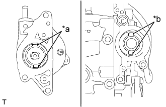 |
Install the vacuum pump assembly while aligning the grooves of the vacuum pump assembly with the claws of the intake camshaft RH.
| *a | Groove of the Vacuum Pump Assembly |
| *b | Claw of the Intake Camshaft |
Install the 3 bolts.
| 29. INSTALL PUMP DRIVE CASE ASSEMBLY |
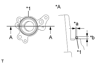 |
Using a sealer gun, apply seal packing in a continuous line as shown in the illustration.
| *A | A-A cross-section |
| *1 | Seal Packing |
| *a | Seal Application Position : Within 1 mm (0.039 in.) from Edge |
| *b | Seal Diameter : 2 to 4 mm (0.079 to 0.158 in.) |
Using a 6 mm hexagon wrench, install the pump drive case assembly with the 3 bolts.
| 30. INSTALL VALVE LIFTER |
Turn the crankshaft until the flat of the cam is facing the cylinder head cover's fuel pump attachment hole.
Apply a coat of engine oil to the pump activation cam and pump lifter part.
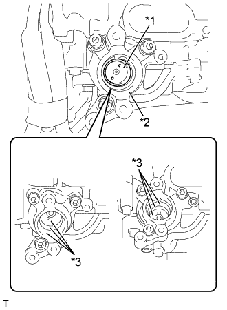 |
Apply new engine oil to the inside of the pump drive case assembly and the underside of the valve lifter, and install the valve lifter to the pump drive case assembly.
| *1 | Valve Lifter |
| *2 | Pump Drive Case Assembly |
| *3 | Location for applying new engine oil |
| 31. INSTALL FUEL PUMP ASSEMBLY |
Apply a light coat of engine oil to a new O-ring and install it to the fuel pump assembly.
Using a "TORX" Plus Socket Wrench, install the fuel pump assembly with the 2 bolts.
| 32. INSTALL NO. 2 FUEL DELIVERY PIPE |
Temporarily install the new No. 2 fuel pipe with the 2 union nuts.
Using a union nut wrench, tighten the 2 union nuts.
| 33. INSTALL INTAKE MANIFOLD |
Install 2 new gaskets to the intake manifold.
Install the intake manifold with the 6 bolts.
Engage the 2 clamps and connect the 4 connectors.
Connect the fuel pump connector.
Connect the No. 1 vacuum switching valve assembly connector.
Connect the vacuum sensor connector.
Connect the 2 water by-pass hoses to the throttle body assembly.
Connect the throttle body assembly connector.
| 34. CONNECT VENTILATION HOSE |
Connect the ventilation hose.
| 35. INSTALL FUEL DELIVERY PIPE SUB-ASSEMBLY |
Install the fuel delivery pipe sub-assembly to the fuel pump assembly with a new gasket and the union bolt.
Connect the No. 2 fuel vapor feed hose.
Install the bolt and connect the fuel delivery pipe sub-assembly.
| 36. INSTALL INJECTOR COVER (for Bank 2) |
Install the injector cover to the intake manifold with the 2 bolts.
| 37. INSTALL INJECTOR COVER (for Bank 1) |
Install the injector cover to the intake manifold with the 2 bolts.
| 38. INSTALL V-RIBBED BELT TENSIONER ASSEMBLY |
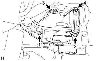 |
Temporarily install the V-ribbed belt tensioner with the 5 bolts.
Tighten the 4 bolts in the order shown in the illustration.
| 39. INSTALL NO. 2 IDLER PULLEY SUB-ASSEMBLY |
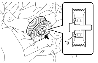 |
Install the washer plate to the No. 2 idler pulley sub-assembly as shown in the illustration.
| *a | Protrusion |
Install the washer plate and No. 2 idler pulley sub-assembly with the bolt.
| 40. INSTALL OIL LEVEL DIPSTICK GUIDE |
Install a new O-ring to the oil level dipstick guide.
Apply a light coat of engine oil to the O-ring.
Install the oil level dipstick guide with the bolt.
Install the oil level dipstick sub-assembly.
| 41. INSTALL GENERATOR ASSEMBLY |
Install the generator assembly with the 2 bolts.
| 42. INSTALL FAN AND GENERATOR V BELT |
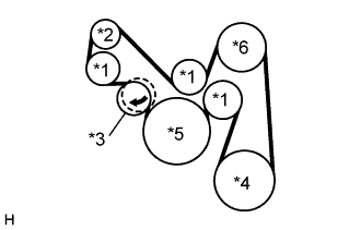 |
Set the fan and generator V belt onto every part.
| *1 | Idler |
| *2 | Generator |
| *3 | Tensioner |
| *4 | Water Pump |
| *5 | Crankshaft |
| *6 | A/C Compressor (w/ Air Conditioning System) |
| Idler Pulley Bracket (w/o Air Conditioning System) |
While turning the belt tensioner clockwise, remove the 3 mm (0.118 in.) hexagon wrench.
Check that the fan and generator V belt fits properly in the ribbed grooves.
| 43. INSTALL BELT GENERATOR COVER |
Install the belt generator cover with the 2 blots.
Engage the 2 wire harness clamps and install the wire harness to the belt generator cover.
| 44. INSTALL GENERATOR COVER |
Install the generator cover with the 2 blots.
| 45. INSTALL ENGINE HANGER |
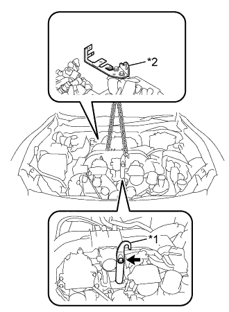 |
Install the engine hanger with the bolt, as shown in the illustration.
| *1 | No. 1 Engine Hanger |
| *2 | No. 2 Engine Hanger |
| No. 1 Engine Hanger | 12281-38030 |
| Bolt | 90119-14120 |
Use an engine sling device and a mini crane to hold the engine.
| 46. REMOVE ENGINE STAND |