 |
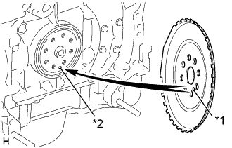
Install the No. 1 crankshaft position sensor plate.
| *1 | Pin Hole |
| *2 | Pin |
- HINT:
- Align the pin of the front drive spacer with the pin hole of the crankshaft.
ENGINE ASSEMBLY > INSTALLATION |
| 1. INSTALL FRONT ENGINE MOUNTING BRACKET |
Install the 2 front engine mounting brackets with the 4 bolts.
| 2. REMOVE ENGINE STAND |
Attach an engine sling device and hang the engine with a chain block.
Remove the engine stand from the engine.
| 3. INSTALL NO. 1 CRANKSHAFT POSITION SENSOR PLATE |
Clean the 8 bolts and 8 bolt holes.
|
Install the No. 1 crankshaft position sensor plate.
| *1 | Pin Hole |
| *2 | Pin |
| 4. INSTALL FLYWHEEL SUB-ASSEMBLY (for Manual Transmission) |
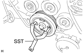 |
Using SST, hold the crankshaft pulley.
Install the flywheel sub-assembly onto the crankshaft.
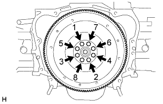 |
In several steps, uniformly install and tighten the 8 bolts in the sequence shown in the illustration.
| 5. INSTALL CLUTCH DISC ASSEMBLY (for Manual Transmission) |
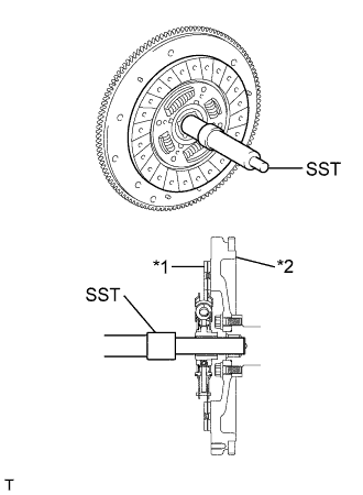 |
Insert SST into the clutch disc assembly, and then insert them both into the flywheel sub-assembly.
| *1 | Clutch Disc Assembly |
| *2 | Flywheel Sub-assembly |
| 6. INSTALL CLUTCH COVER ASSEMBLY (for Manual Transmission) |
Reuse the flywheel sub-assembly and clutch cover assembly:
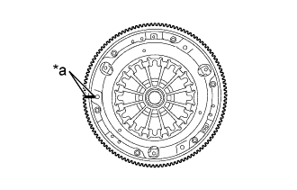 |
Align the matchmark on the clutch cover assembly with that on the flywheel sub-assembly.
| *a | Matchmark |
Replace the flywheel sub-assembly or clutch cover assembly:
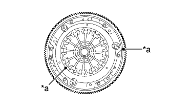 |
Position the clutch cover assembly so that there is a gap of at least 120° between the unbalance marks on the flywheel sub-assembly and the clutch cover assembly.
| *a | Unbalance Mark |
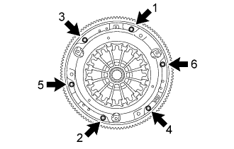 |
Following the procedures shown in the illustration, tighten the 6 bolts in order, starting with the bolt located near the knock pin at the top.
| 7. INSTALL DRIVE PLATE AND RING GEAR SUB-ASSEMBLY (for Automatic Transmission) |
|
Using SST, hold the crankshaft pulley.
Install the drive plate and ring gear sub-assembly and rear drive plate spacer onto the crankshaft.
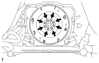 |
In several steps, uniformly install and tighten the 8 bolts in the sequence shown in the illustration.
| 8. INSTALL ENGINE ASSEMBLY |
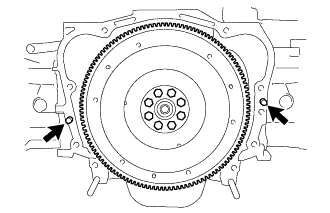 |
Confirm that 2 knock pins are on the transmission contact surface of the engine block before transmission installation.
Keeping the engine assembly and the transmission assembly in a horizontal position, align the knock pins with each hole on the transmission assembly and install the bolt.
| 9. REMOVE ENGINE HANGER |
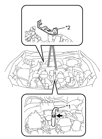 |
Install the engine hanger with the bolt, as shown in the illustration.
| *1 | No. 1 Engine Hanger |
| *2 | No. 2 Engine Hanger |
| No. 1 Engine Hanger | 12281-38030 |
| Bolt | 90119-14120 |
Use an engine sling device and a mini crane to hold the engine.
| 10. CONNECT FUEL HOSE |
for Clamp Type:
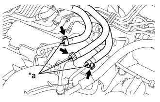 |
Connect the fuel tube and No. 2 fuel tube and fuel tube to the fuel pipe.
| *a | Matchmark |
for Metal Type:
Connect the fuel tube and No. 2 fuel tube to the fuel pipe (Click here).
Connect the No. 2 fuel vapor feed hose to the fuel pipe.
| 11. INSTALL DRIVE PLATE SETTING HEXAGON BOLT (for Automatic Transmission) |
Install the 6 drive plate and torque converter setting bolt.
| 12. INSTALL FLYWHEEL HOUSING UNDER COVER |
Install the flywheel housing side cover.
| 13. INSTALL FRONT CROSS MEMBER SUB-ASSEMBLY |
Install the front suspension crossmember sub-assembly with the 2 nuts.
| 14. INSTALL MANUAL TRANSMISSION ASSEMBLY (for Manual Transmission) |
Install the 3 bolts and 2nuts.
| 15. INSTALL AUTOMATIC TRANSMISSION ASSEMBLY (for Automatic Transmission) |
Install the 3 bolts and 2nuts.
| 16. INSTALL FRONT STABILIZER BAR (for Automatic Transmission) |
| 17. INSTALL ENGINE UNDER COVER REAR LH (w/ Floor Under Cover) |
Install the rear engine under cover LH with the 3 bolts and 8 clips.
| 18. INSTALL EARTH CABLE |
Install the 2 grounded cables with the 2 bolts.
| 19. CONNECT RADIATOR OUTLET HOSE |
Install the clamp and connect the radiator outlet hose.
| 20. CONNECT NO. 3 TRANSMISSION OIL COOLER HOSE (for Automatic Transmission) |
Connect the No. 3 transmission oil cooler hose.
| 21. INSTALL STARTER ASSEMBLY (for Automatic Transmission) |
| 22. INSTALL STARTER ASSEMBLY (for Manual Transmission) |
| 23. CONNECT NO. 1 COOLER REFRIGERANT DISCHARGE HOSE (w/ Air Conditioning System) |
Remove the attached vinyl tape from the hose.
Apply sufficient compressor oil to a new O-ring and the fitting surface of the compressor with magnet clutch.
Install the O-ring onto the No. 1 cooler refrigerant discharge hose.
Install the No. 1 cooler refrigerant discharge hose onto the compressor with magnet clutch with the bolt.
| 24. INSTALL SUCTION HOSE SUB-ASSEMBLY (w/ Air Conditioning System) |
Remove the attached vinyl tape from the hose.
Apply sufficient compressor oil to a new O-ring and the fitting surface of the compressor assembly with pulley.
Install the O-ring onto the suction hose sub-assembly.
Install the suction hose sub-assembly onto the compressor assembly with pulley with the bolt.
Remove the vinyl tape from the pipe.
Sufficiently apply compressor oil to a new O-ring and the fitting surface of the suction pipe sub-assembly.
Connect the O-ring to the suction pipe sub-assembly.
Connect the suction pipe sub-assembly.
Rotate the hook connector in the direction indicated by the arrow in the illustration.
for LHD:
Install the suction hose sub-assembly with the nut.
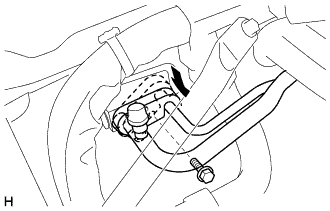 |
Insert the pipe joint into the cooler expansion valve securely and tighten the bolt.
for RHD:
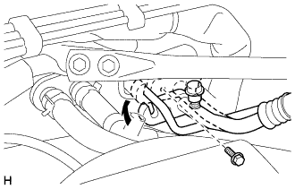 |
Insert the pipe joint into the cooler expansion valve securely and tighten the bolt.
| 25. INSTALL NO. 1 TRANSMISSION OIL COOLER HOSE (for Automatic Transmission) |
Connect the No. 1 transmission oil cooler hose.
| 26. CONNECT HEATER WATER HOSE |
Install the 2 hose clamps and connect 2 heater water hoses.
| 27. INSTALL EXHAUST MANIFOLD |
| 28. CONNECT VACUUM TUBE CONNECTOR HOSE (for Manual Transmission) |
Connect the vacuum tube connector hose with the bolt.
Connect the vacuum tube connector hose.
| 29. CONNECT VACUUM TUBE CONNECTOR HOSE (for Automatic Transmission) |
Connect the vacuum tube connector hose with the 2 bolts.
Connect the vacuum tube connector hose.
| 30. INSTALL NO. 1 ENGINE COVER SUB-ASSEMBLY (w/ Air Conditioning System) |
Engage the 3 claws and install the No. 1 engine cover sub-assembly.
| 31. CONNECT ENGINE WIRE (for RHD) |
Connect the generator connector and connect the clamp.
Connect the generator wire with the nut.
Install the terminal cap.
Connect the 5 wire harness clamps.
Install the 2 wire harness clamp brackets with the 2 bolts.
Connect the 2 wire harness clamps to the 2 wire harness clamp brackets.
Connect the wire harness clamp to the No. 2 engine hanger.
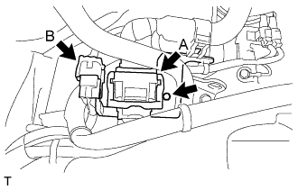 |
Connect the connector (B).
Connect the wire harness connector (A) and securely lock the connector.
Install the wire harness clamp bracket to the No. 2 engine hanger with the bolt.
for Automatic Transmission:
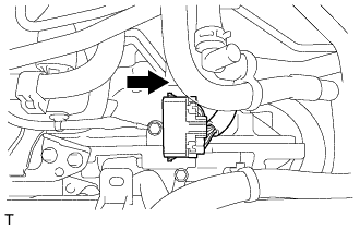 |
Slide the connector in the direction shown in the diagram, and connect the wire harness.
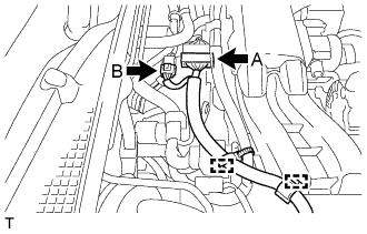 |
Connect the 2 wire harness clamps.
Connect the wire harness connector (A) and securely lock the connector.
Connect the connector (B).
| 32. CONNECT ENGINE WIRE (for LHD) |
Connect the generator connector and connect the clamp.
Connect the generator wire with the nut.
Install the terminal cap.
Connect the 5 wire harness clamps.
Install the 2 wire harness clamp brackets with the 2 bolts.
Connect the 2 wire harness clamps to the 2 wire harness clamp brackets.
Connect the wire harness clamp to the No. 2 engine hanger.
|
Connect the connector (B).
Connect the wire harness connector (A) and securely lock the connector.
Install the wire harness clamp bracket to the No. 2 engine hanger with the bolt.
for Automatic Transmission:
|
Slide the connector in the direction shown in the diagram, and connect the wire harness.
Connect the 2 wire harness clamps.
Connect the wire harness connector (A) and securely lock the connector.
Connect the connector (B).
| 33. INSTALL INJECTOR DRIVER |
Install the injector driver with the 3 bolts.
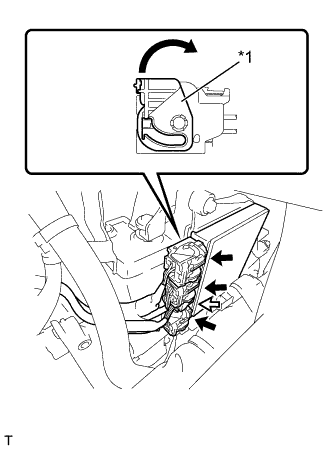 |
Connect the 4 connectors to the injector driver. Move the lock levers in the direction indicated by the arrow to lock the 3 connectors.
| *1 | Lock Lever |
 | Lock with Connector |
 | Normal Connector |
| 34. INSTALL WATER FILLER SUB-ASSEMBLY |
Install the 2 clamps and connect the water filler sub-assembly.
Install the water filler sub-assembly with 2 bolts.
| 35. INSTALL RADIATOR RESERVE TANK ASSEMBLY |
Install the radiator reserve tank assembly with the 2 bolts.
| 36. INSTALL AIR CLEANER ASSEMBLY WITH HOSE |
Install the stay with bolt to the body.
Install the air cleaner assembly with hose with the 3 bolts.
Install the hose clamp.
Connect the clamp and wire harness to the air cleaner cap.
Connect the mass air flow meter connector.
Connect the No. 2 ventilation hose.
Install the 2 bolts and the chamber duct with chamber.
Connect the hose.
| 37. INSTALL FRONT SUSPENSION UPPER TO COWL BRACE SUB-ASSEMBLY LH |
Install the front suspension upper to cowl brace sub-assembly with the new bolt and 3 new nuts.
| 38. INSTALL FRONT SUSPENSION UPPER TO COWL BRACE SUB-ASSEMBLY RH |
| 39. ADD ENGINE OIL |
Add new engine oil and install the oil filler cap.
| Oil Grade | Oil Viscosity (SAE) |
|
|
| Item | Capacity |
| Drain and refill with oil filter change | 5.4 liters (5.7 US qts, 4.8 Imp. qts) |
| Drain and refill without oil filter change | 5.2 liters (5.5 US qts, 4.6 Imp. qts) |
| Dry fill | 6.3 liters (6.7 US qts, 5.5 Imp. qts) |
| 40. CONNECT CABLE TO NEGATIVE BATTERY TERMINAL |
| 41. ADD ENGINE COOLANT |
Tighten the radiator drain cock plug.
Pour in coolant of the specified density until it reaches the base of the entrance to the water inlet.
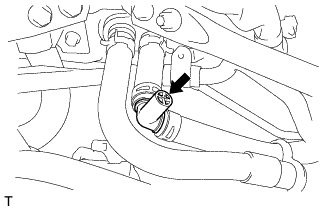 |
Open the air bleed plug on the heater hose side. (for LHD)
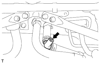 |
Open the air bleed plug on the heater hose side. (for RHD)
If the water level in the entrance to the water inlet drops, pour coolant in until it reaches the base of the entrance to the water inlet.
Close the air bleed plug when the coolant begins to come out of the air bleed valve on the heater hose side.
Pour in coolant of the specified concentration until it reaches the "FULL" level of the radiator reserve tank.
Close the radiator cap. [*1]
Start the engine, race it 5 to 6 times at under 3000 rpm or less, and then stop the engine. [*2]
1 minute after stopping the engine, remove the radiator cap and pour coolant in if the water level in the entrance to the water inlet has dropped. [*3]
Repeat operations [*1], [*2], and [*3] until the water level in the entrance to the water inlet does not drop.
Close the radiator cap and the radiator reserve tank cap.
Start the engine, set the heater on full warm, and then run it with the blower speed set to "LO".
Run the engine at 2000 rpm or less until the radiator fan starts and stops. [*4]
Stop the engine and wait until the coolant temperature drops to 30 °C (86 °F) or less. [*5]
Remove the radiator cap and, if the volume of coolant has dropped, pour coolant in until it reaches the base of the entrance to the water inlet and until it reaches the "FULL" level in the radiator reserve tank. [*6]
Close the radiator cap. [*7]
Set the heater to full warm, and, with the blower speed set to "LO", race the engine at 3000 rpm or less. [*8]
At this point, if the engine coolant can be heard flowing in the heater core, repeat operations [*4], [*5], [*6], [*7], and [*8].
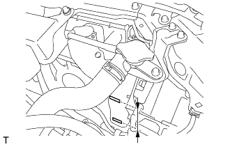 |
When the water level no longer drops, adjust the water level so that the water level in the radiator reserve tank reaches the "FULL" line.
| 42. CHARGE WITH REFRIGERANT (w/ Air Conditioning System) |
for HFC-134a (R134a):
(Click here)
for HFO-1234fy (R1234fy):
(Click here)
| 43. CHECK FOR ENGINE COOLANT LEAK |
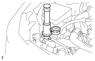 |
Fill the radiator with coolant and attach a radiator cap tester.
Warm up the engine.
Using a radiator cap tester, increase the pressure inside the radiator to 137 kPa (1.4 kgf/cm2, 20 psi), and check that the pressure does not drop.
If the pressure drops, check the hoses, radiator and water pump for leaks. If no external leaks are found, check the heater core, cylinder block and cylinder head.
| 44. CHECK FOR ENGINE OIL LEAK |
Start the engine. Make sure that there are no oil leaks from the connection point of the oil filter sub-assembly.
| 45. CHECK FOR FUEL LEAK |
Connect the GTS to the DLC3.
Turn the ignition switch to ON.
Turn the GTS on.
Enter the following menus: Power train / Engine / Active Test / Control the Fuel Pump / Speed.
Check the fuel pump operation.
Check for pressure in the fuel inlet tube from the fuel line. Check that sound of fuel flowing in the fuel tank can be heard.
If no sound can be heard, check the EFI MAIN 1 relay, fuel pump, ECM and wiring connector.
Inspect for fuel leaks.
Check that there are no fuel leaks anywhere on the system after performing maintenance.
If there is a fuel leak, repair or replace parts as necessary.
| 46. CHECK FOR EXHAUST GAS LEAK |
If gas is leaking, tighten the areas necessary to stop the leak. Replace the damaged parts as necessary.
| 47. INSPECT FOR REFRIGERANT LEAK |
for HFC-134a (R134a):
for HFO-1234fy (R1234fy):
| 48. INSPECT THROTTLE WITH MOTOR BODY ASSEMBLY |
Turn the ignition switch to ON without operating the accelerator pedal.
Connect the GTS to the DLC3 and clear the DTCs (Click here).
Start the engine and check that the MIL is not illuminated. After the engine is warmed up, check that the idle speed is within the specified range when the A/C is switched off.
| Condition | Engine Idle Speed |
| A/C switched off | 650 to 800 rpm |
Enter the following menus: Data List / Throttle Sensor Volt%. Fully depress the accelerator pedal and check that the value is 80 to 90%.
Perform a road test and confirm that there are no abnormalities.
| 49. INSPECT IGNITION TIMING |
Warm up and stop the engine.
When using the GTS:
Connect the GTS to the DLC3.
Start the engine and idle it.
Turn the GTS on.
Enter the following menus: Powertrain / Engine and ECT / Data List / IGN Advance.
Check that the ignition timing advances immediately when the engine speed is increased.
When not using the GTS:
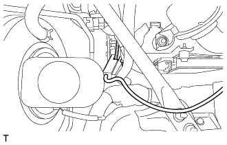 |
Connect the tester probe of a timing light to the wire of the ignition connector for the No. 1 cylinder.
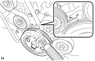 |
Using the timing light, check the ignition timing.
Check that the ignition timing advances immediately when the engine speed is increased.
Disconnect the timing light from the engine.
| 50. INSPECT ENGINE IDLE SPEED |
Warm up and stop the engine.
When using the GTS:
Connect the GTS to the DLC3.
Race the engine at 2500 rpm for approximately 90 seconds.
Turn the GTS on.
Enter the following menus: Powertrain / Engine and ECT / Data List / Engine Speed.
| Transmission | Idling Speed |
| for Automatic Transmission | 600 to 800 rpm |
| for Manual Transmission | 550 to 750 rpm |
Disconnect the GTS from the DLC3.
| 51. INSPECT CO/HC |
Start the engine.
Maintain the engine speed at 2500 rpm for approximately 180 seconds.
Insert a CO/HC meter testing probe at least 40 cm (1.31 ft) into the tailpipe during idling.
Immediately check the CO/HC concentration at idle and/or 2500 rpm.
Check the A/F sensor (Click here) and heated oxygen sensor (Click here) operation.
Refer to the table below for the possible cause, and then inspect and correct the applicable causes if necessary.
| CO | HC | Symptom | Causes |
| Normal | High | Rough idle |
|
| Low | High | Rough idle (Fluctuating HC reading) |
|
| High | High | Rough idle (Black smoke from exhaust) |
|
| 52. INSPECT ENGINE COOLANT LEVEL |
|
Check that the engine coolant level is between the low and full lines when the engine is cold.
If the engine coolant level is low, check for leaks and add TOYOTA Genuine 50/50 Pre-mixed Super Long Life Coolant BLUE or similar high quality ethylene glycol based non-silicate, non-amine, non-nitrite and non-borate coolant with long-life hybrid organic acid technology to the full line.
| 53. INSPECT ENGINE OIL LEVEL |
Park the vehicle in a level place.
With the engine turned off, check that the engine oil level is between the full level and low level marks.
If low, check for leakage and add oil up to the full level mark.
| 54. SET HOOD SUB-ASSEMBLY |
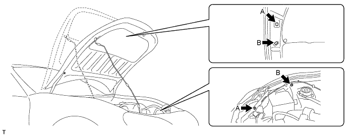
Change the front hood stay position from B to A, and store the front hood stay.