TIMING CHAIN > REMOVAL |
| 1. REMOVE TIMING CHAIN OR BELT COVER SUB-ASSEMBLY |
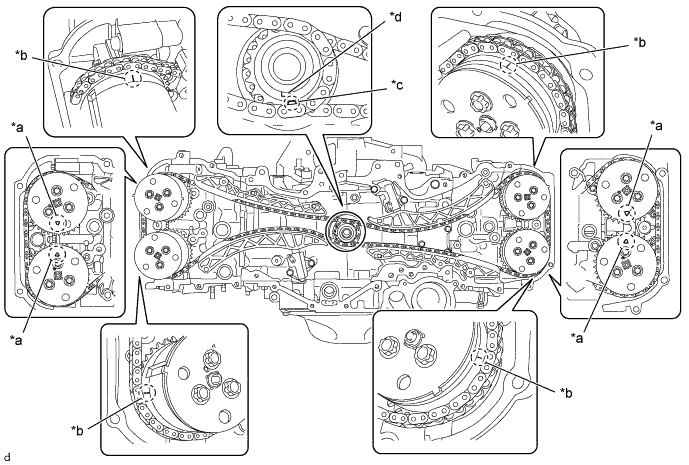
| 2. MAKE PAINT MARKS |
| *a | Triangular Mark | *b | Engraved Line |
| *c | Oval Mark | *d | Crankshaft Timing Gear key |
| 3. REMOVE CHAIN SUB-ASSEMBLY (for Bank 1) |
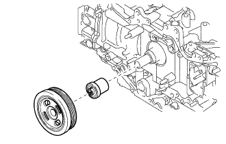 |
Temporarily install the crankshaft pulley spacer and crankshaft pulley.
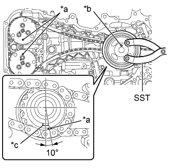 |
Using SST, turn the crankshaft pulley clockwise until the alignment marks on the camshaft timing intake gear assembly RH and the camshaft timing exhaust gear assembly RH, and the crankshaft pulley pin hole are aligned at the positions shown in the illustration.
| *a | Alignment Mark |
| *b | Crankshaft Pulley Pin Hole |
| *c | Crankshaft Timing Gear key |
Remove the crankshaft pulley and crankshaft pulley spacer.
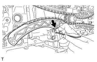 |
Push down the chain tensioner slipper and insert a 2.5 mm (0.098 in.) hexagonal wrench through the stopper plate into the No. 1 chain tensioner assembly.
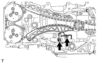 |
Remove the 2 bolts and No. 1 chain tensioner assembly.
Remove the chain tensioner slipper.
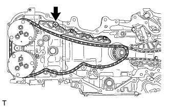 |
Using a 5 mm hexagonal wrench, remove the bolt and No. 1 chain vibration damper.
Remove the chain sub-assembly.
| 4. REMOVE CHAIN SUB-ASSEMBLY (for Bank 2) |
Temporarily install the crankshaft pulley spacer and crankshaft pulley.
Using SST, turn the crankshaft pulley clockwise until the alignment marks on the camshaft timing intake gear assembly LH and the camshaft timing exhaust gear assembly LH, and the crankshaft pulley pin hole are aligned at the positions shown in the illustration.
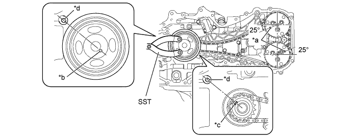
| *a | Alignment Mark | *b | Crankshaft Pulley Pin Hole |
| *c | Crankshaft Timing Gear key | *d | Cylinder Block Guide Pin |
Remove the crankshaft pulley and crankshaft pulley spacer.
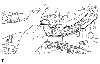 |
Push the chain tensioner slipper and retain the plunger by inserting an approximately 1 mm (0.039 in.) wire through the stopper plate into the No. 2 chain tensioner assembly.
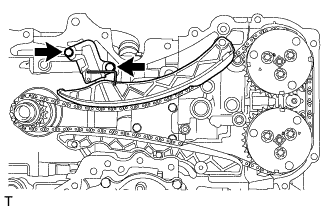 |
Remove the 2 bolts and No. 2 chain tensioner assembly.
Remove the chain tensioner slipper.
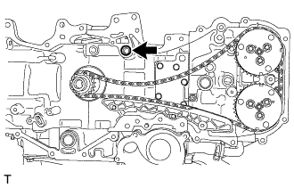 |
Remove the O-ring from the cylinder block (bank 2).
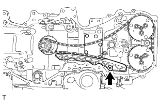 |
Using a 5 mm socket hexagon wrench, remove the bolt and No. 1 chain vibration damper.
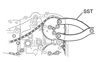 |
While releasing the tension of chain sub-assembly using SST, remove the chain sub-assembly.
| 5. INSPECT CHAIN SUB-ASSEMBLY |
Check the chain sub-assembly for deformation, cracks or other damages.
If the chain sub-assembly has any defects, replace it.