BODY PANEL FIT STANDARD / ADJUSTMENT METHOD ADJUSTMENT
Check that the clearance measurements of areas *a through *e are within each standard range.
INSPECT HOOD SUB-ASSEMBLY
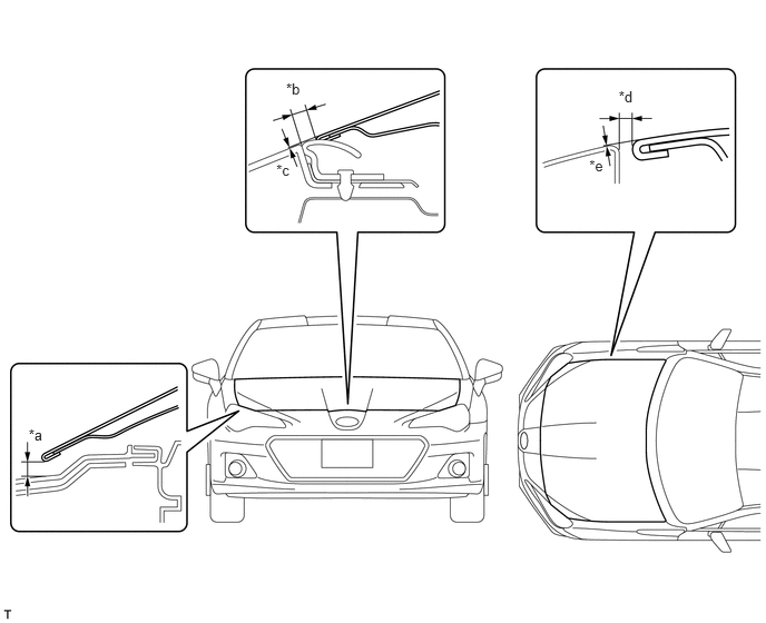
| Area | Measurement | Area | Measurement |
|---|---|---|---|
| *a | 5.8 to 9.8 mm (0.2283 to 0.3858 in.) | *b | 3.0 to 7.0 mm (0.1181 to 0.2756 in.) |
| *c | -2.0 to 2.0 mm (-0.0787 to 0.0787 in.) | *d | 2.0 to 5.0 mm (0.0787 to 0.1969 in.) |
| *e | -2.0 to 1.0 mm (-0.0787 to 0.0394 in.) | - | - |
- HINT:
- ·
Use the same procedure for the LHD and RHD vehicles.
·The procedure listed below is for the LHD vehicles.
·Centering bolts are used to mount the hood hinge and hood lock. The hood and hood lock cannot be adjusted with the centering bolts installed. Substitute the centering bolts with standard bolts when making adjustments.
ADJUST HOOD SUB-ASSEMBLY
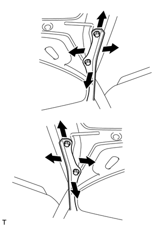
Horizontally and vertically adjust the hood.
Loosen the 4 hinge bolts of the hood.
Adjust the clearance between the hood and front fender by moving the hood.
Tighten the 4 hinge bolts after the adjustment.
- Torque:
- 18 N*m (184 kgf*cm, 13 ft.*lbf)
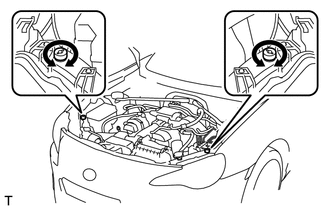
Adjust the height of the front end of the hood using the cushion rubbers.
Adjust the 2 cushion rubbers so that the heights of the hood and fender are aligned.
- HINT:
-
Raise or lower the front end of the hood by turning the 2 cushion rubbers.
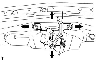
Adjust the hood lock.
Loosen the 3 bolts.
Adjust the hood lock position so that the striker can enter it smoothly.
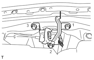
Tighten the 3 bolts after the adjustment in the order shown in the illustration.
- Torque:
- 33 N*m (337 kgf*cm, 24 ft.*lbf)
Check that the striker can engage smoothly with the hood lock.
INSPECT FRONT DOOR
Check that the clearance measurements of areas *a through *j are within each standard range.
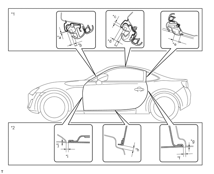
| Area | Measurement | Area | Measurement |
|---|---|---|---|
| *a | 0.5 mm (0.0197 in.) | *b | 7.0 mm (0.2756 in.) |
| *c | 5.0 mm (0.1969 in.) | *d | 6.7 mm (0.2638 in.) |
| *e | 13.5 to 16.5 mm (0.5315 to 0.6496 in.) | *f | 2.5 to 5.5 mm (0.0984 to 0.2165 in.) |
| *g | 0.0 to 1.5 mm (0.0 to 0.0591 in.) | *h | 4.8 to 7.8 mm (0.1890 to 0.3071 in.) |
| *i | 3.1 to 5.6 mm (0.122 to 0.220 in.) | *j | -1.0 to 1.5 mm (-0.0394 to 0.0591 in.) |
| *1 | Front Glass | *2 | Front Door |
- HINT:
- ·
Use the same procedure for both the RH and LH sides.
·The following procedure is for the LH side.
·Centering bolts are used to mount the door hinge to the vehicle body and door. The door cannot be adjusted with the centering bolts installed on it. Substitute the centering bolts with standard bolts when making adjustments.
ADJUST FRONT DOOR GLASS
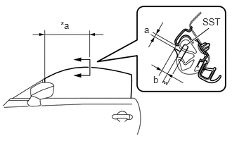
Insert SST as shown in the illustration.
- SST
- 09812-18010
Using a SST, check that the clearance measurements of areas "a" to "b" are within each standard range
- SST
- 09812-18010
- Standard Clearance:
Area Measurement a 5.0 mm (0.1969 in.) b 6.7 mm (0.2638 in.)
| *a | 400 mm (15.7 in.) |
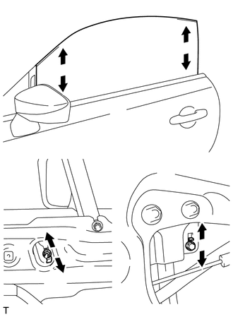
Adjust the front door glass so that the fitting dimensions come within the reference values.
Loosen the nut on the front door sush stopper and front door rear sush stopper, and adjust the glass position.
After the adjustment, tighten the nut on the front door sush stopper and front door rear sush stopper.
- Torque:
- 7.5 N*m (76 kgf*cm, 66 in.*lbf)
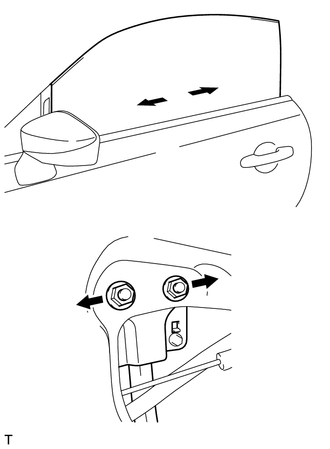
Loosen the 2 nuts on the front door rear lower frame sub-assembly, and adjust the glass position.
After the adjustment, tighten the 2 nuts on the front door rear lower frame sub-assembly.
- Torque:
- 14 N*m (143 kgf*cm, 10 ft.*lbf)
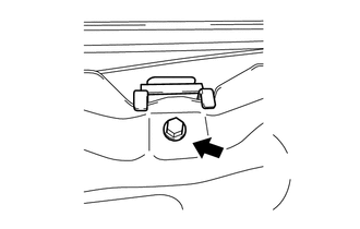
Loosen the bolt on the door glass inner stabilizer.
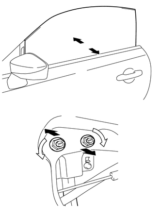
Loosen the bolt on the door glass inner stabilizer and adjust the glass position.
Loosen the 2 nuts on the front door rear lower frame sub-assembly.
After the adjustment, tighten the 2 nuts on the front door rear lower frame sub-assembly.
- Torque:
- 14 N*m (143 kgf*cm, 10 ft.*lbf)
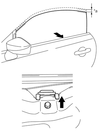
Tighten the bolt on the door glass inner stabilizer.
Lower the front door glass approximately 20.0 mm (0.7874 in.).
| *a | 20.0 mm (0.7874 in.) |
Push the front door glass toward the outside of the vehicle.
While pushing the front door glass and the door glass inner stabilizer toward the outside of the vehicle, tighten the bolt on the door glass inner stabilizer.
- Torque:
- 7.5 N*m (76 kgf*cm, 66 in.*lbf)
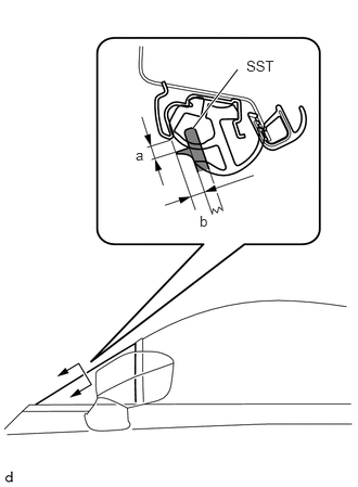
Using a SST, check that the clearance measurements of areas "a" to "b" are within each standard range .
- SST
- 09812-18020
- Standard Clearance:
Area Measurement a 2.5 to 5.5 mm (0.0984 to 0.2165 in.) b 5.2 to 8.2 mm (0.2047 to 0.3228 in.)
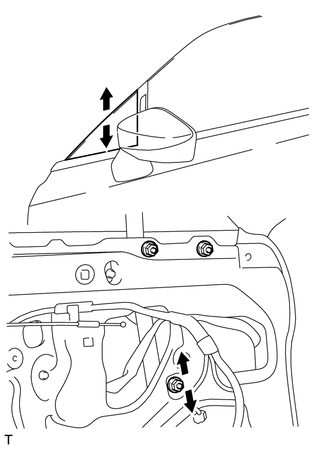
Adjust the front door sush so that the fitting dimensions come within the reference values.
Loosen the nut on the front door sush and adjust the front door sush position.
After the adjustment, tighten the nut on the front door sush.
- Torque:
- 14 N*m (143 kgf*cm, 10 ft.*lbf)
ADJUST FRONT DOOR
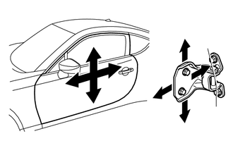
Loosen the hinge bolts on the vehicle body and adjust the door position.
Loosen the hinge bolts on the door and adjust the door position.
After the adjustment, tighten the hinge bolts on the door.
- Torque:
- 25 N*m (255 kgf*cm, 18 ft.*lbf)
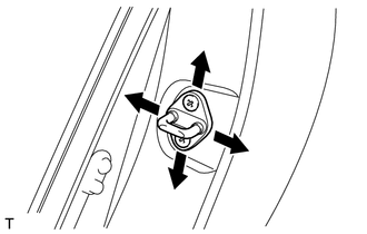
Adjust the striker position by slightly loosening the striker mounting screws and hitting the striker with a plastic-faced hammer.
After the adjustment, tighten the striker mounting screws.
- Torque:
- 18 N*m (184 kgf*cm, 13 ft.*lbf)
INSPECT LUGGAGE COMPARTMENT DOOR PANEL SUB-ASSEMBLY
Check that the clearance measurements of areas *a to *f are within each standard range.
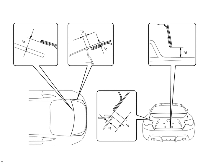
- Standard Clearance:
Area Measurement Area Measurement *a 8.2 mm (0.3228 in.) *b 2.0 to 5.0 mm (0.0787 to 0.1969 in.) *c -2.0 to 1.0 mm (-0.0787 to 0.0394 in.) *d 5.8 to 10.2 mm (0.2283 to 0.4016 in.) *e 4.3 to 7.3 mm (0.1693 to 0.2874 in.) *f -2.0 to 1.0 mm (-0.0787 to 0.0394 in.)
- HINT:
-
Centering bolts are used to mount the door hinge to the vehicle body and door. The door cannot be adjusted with the centering bolts on. Substitute the centering bolts with standard bolts when making adjustments.
ADJUST LUGGAGE COMPARTMENT DOOR PANEL SUB-ASSEMBLY
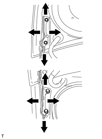
Horizontally and vertically adjust the door by loosening the door side hinge bolts.
- Torque:
- 18 N*m (184 kgf*cm, 13 ft.*lbf)
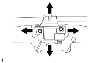
When adjusting the rear edge of the doors left or right, or adjusting the luggage door closer assembly, loosen the bolts before making adjustments.
Using a brass bar and a hammer, hit the striker to adjust its position.
After the adjustment, tighten the 2 bolts on the luggage door closer assembly.
- Torque:
- 7.5 N*m (76 kgf*cm, 66 in.*lbf)