Home › Drivetrain › TL70 MANUAL TRANSMISSION / TRANSAXLE › MANUAL TRANSMISSION SYSTEM › 2012.03–2014.05
NM2090E _52 Drivetrain _060630 TL70 MANUAL TRANSMISSION / TRANSAXLE _0297326 MANUAL TRANSMISSION SYSTEM UN GENERAL/CONTROL/DETAILS F

TL70 MANUAL TRANSMISSION / TRANSAXLE  MANUAL TRANSMISSION SYSTEM  GENERAL/CONTROL/DETAILS  DETAILS  


CONSTRUCTION


a.

Gear Train

i.

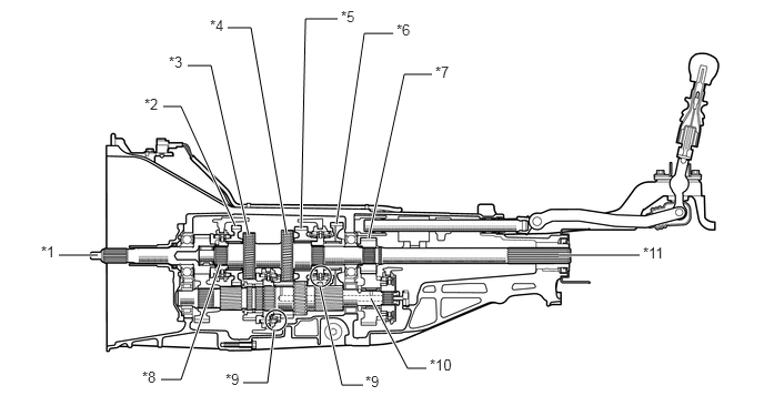
The transmission synchromesh mechanism is an all-speed constant mesh type.

Gear 1st, 2nd and 3rd 4th, 5th, 6th and Reverse
Synchromesh mechanism type Triple-cone Single-cone

X108369E02
5.24,2.396 6,2.396 true 0.552,2.396 0.917,2.396 true 2.063,2.479 1.698,3.563 1.698,3.563 1.51,3.563 true 3.156,2.104 3.417,0.313 3.417,0.313 3.688,0.313 true 2.823,2.146 2.865,0.177 2.865,0.177 3.167,0.177 true 2.208,2.125 1.698,1 1.698,1 1.531,1 true 3.479,2.802 3.823,3.458 3.823,3.458 4,3.458 true 3,2.688 3.208,3.615 3.208,3.615 3.406,3.615 true 2.688,2.198 2.354,0.26 2.354,0.26 2.135,0.26 true 2.573,3.094 2.51,3.594 2.51,3.594 2.281,3.594 true 1.76,0.615 1.979,0.615 1.979,0.615 2.333,2.208 true 3.458,2.24 3.792,0.698 3.792,0.698 4.052,0.698 true 3.198,0.073 3.406,0.281 0.208,0.208 10 false *5 1.969,0.156 2.146,0.396 0.177,0.24 10 false *4 1.583,0.5 1.75,0.74 0.167,0.24 10 false *3 4.083,0.594 4.323,0.865 0.24,0.271 10 false *7 3.719,0.198 3.917,0.438 0.198,0.24 10 false *6 1.354,0.896 1.531,1.115 0.177,0.219 10 false *2 1.333,3.458 1.521,3.698 0.188,0.24 10 false *8 0.385,2.281 0.552,2.51 0.167,0.229 10 false *1 6.031,2.292 6.365,2.563 0.333,0.271 10 false *11 2.115,3.479 2.302,3.698 0.188,0.219 10 false *9 3.427,3.5 3.615,3.708 0.188,0.208 10 false *9 4.031,3.344 4.344,3.583 0.313,0.24 10 false *10

Text in Illustration
*1 Input Shaft *2 Reverse Gear
*3 4th Gear *4 3rd Gear
*5 2nd Gear *6 1st Gear
*7 6th Gear *8 5th Gear
*9 Triple-cone Type Synchromesh Mechanism *10 Counter Shaft
*11 Output Shaft - -


b.

Shift Control Mechanism

i.

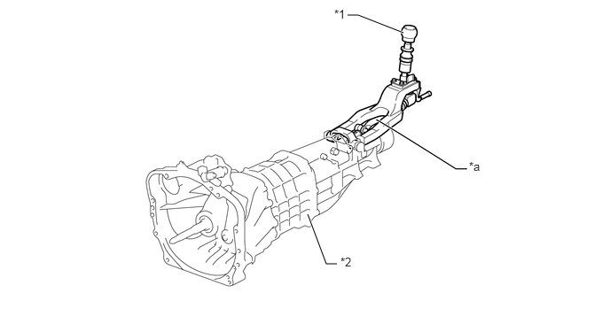
The shift control mechanism uses the semi-direct method to achieve short stroke and good rigidity.


ii.

Friction is lowered during operation by the adoption of slide ball bearings in the shift fork shaft support part, improving the feel of shifting while driving as well as when at a standstill.


iii.

Resin or leather gearshift lever knob is available according to specifications.
U147303E02
4.74,0.385 4.208,0.177 4.208,0.177 4.083,0.177 true 3.615,2.521 3.833,3.104 3.833,3.104 3.958,3.104 true 3.927,0.083 4.125,0.281 0.198,0.198 10 false *1 5.51,1.875 5.802,2.146 0.292,0.271 10 false *a 4,3 4.24,3.271 0.24,0.271 10 false *2

Text in Illustration
*1 Shift Lever Knob *2 Manual Transmission Assembly
*a Semi-Direct Mechanism - -


iv.

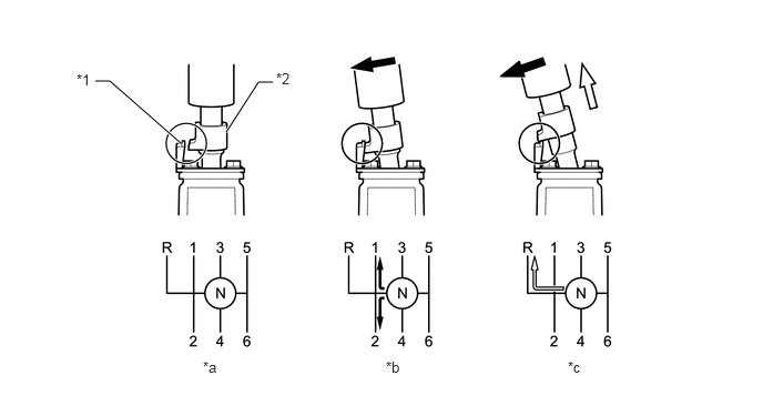
The reverse miss shift prevention mechanism prevents shifting into reverse unless the shift lock release collar provided on the shift lever is raised.


v.

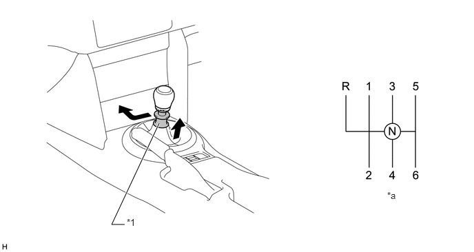
A pull-collar gearshift lever has been adopted to prevent incorrect operation while in forward or in reverse.
X108368E02
1.885,3.396 1.688,3.396 1.688,3.396 2.406,1.865 true 1.917,3.281 2.104,3.531 0.188,0.25 10 false *1 5.854,2.875 6.115,3.135 0.26,0.26 10 false *a

Text in Illustration
*1 Pull Collar - -
*a Shift Pattern - -


vi.

A stopper cover is provided on the 1st-2nd side, so that the pull collar must be pulled upward in order to shift into reverse. This reduces the amount of shift effort and ensures a precise shifting operation.
X108767E02
1.698,1.344 1.031,0.76 1.031,0.76 0.896,0.76 true 2.125,1.24 2.427,0.771 2.427,0.771 2.563,0.771 true 0.719,0.667 0.896,0.896 0.177,0.229 10 false *1 2.594,0.656 2.823,0.938 0.229,0.281 10 false *2 1.906,3.365 2.146,3.635 0.24,0.271 10 false *a 3.625,3.365 3.896,3.635 0.271,0.271 10 false *b 5.333,3.365 5.594,3.615 0.26,0.25 10 false *c

Text in Illustration
*1 Stopper Cover *2 Pull Collar
*a Neutral *b 1st/2nd
*c Reverse - -
V100135

Select Direction
V100136

Pulled-Up


c.

Shift and select mechanism

i.

The shift mechanism has 4 shift forks, 5 shift fork shafts, and an interblock.


ii.

Friction is lowered during operation by the adoption of slide ball bearings in the shift fork shaft support part, improving the feel of shifting while driving as well as when at a standstill.
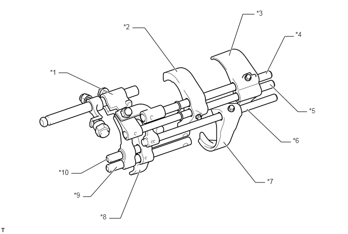
X108370E02
4.719,1.146 5,0.292 5,0.292 5.24,0.292 true 5.479,1.521 5.865,0.75 5.865,0.75 6.052,0.75 true 5.563,1.74 6.135,2.302 6.135,2.302 6.323,2.302 true 5.083,2.25 5.792,2.927 5.792,2.927 5.99,2.927 true 4.604,2.927 5.26,3.76 5.26,3.76 5.458,3.76 true 2.885,3.5 2.479,4.5 2.479,4.5 2.25,4.5 true 2.406,3.438 1.865,4.052 1.865,4.052 1.708,4.052 true 2.219,3.271 1.667,3.573 1.667,3.573 1.469,3.573 true 3.646,1.479 2.979,0.573 2.979,0.573 2.729,0.573 true 2.323,1.948 1.385,1.5 1.385,1.5 1.208,1.5 true 1.521,3.938 1.719,4.156 0.198,0.219 10 false *9 2.063,4.385 2.26,4.625 0.198,0.24 10 false *8 1.031,1.406 1.219,1.635 0.188,0.229 10 false *1 2.542,0.469 2.74,0.698 0.198,0.229 10 false *2 5.281,0.188 5.49,0.438 0.208,0.25 10 false *3 6.083,0.625 6.292,0.854 0.208,0.229 10 false *4 6.365,2.198 6.594,2.427 0.229,0.229 10 false *5 6.031,2.813 6.25,3.052 0.219,0.24 10 false *6 5.5,3.656 5.74,3.927 0.24,0.271 10 false *7 1.208,3.469 1.5,3.698 0.292,0.229 10 false *10

Text in Illustration
*1 Interlock Block *2 1st-2nd Shift Fork
*3 5th Reverse Shift Fork *4 Main Shift Fork Shaft
*5 No. 2 Shift Fork Shaft *6 No. 3 Shift Fork Shaft
*7 3rd-4th Shift Fork *8 6th Shift Fork
*9 No. 5 Shift Fork Shaft *10 No. 4 Shift Fork Shaft


iii.

Friction is lowered during operation by the adoption of slide ball bearings in the shift fork shaft support part.
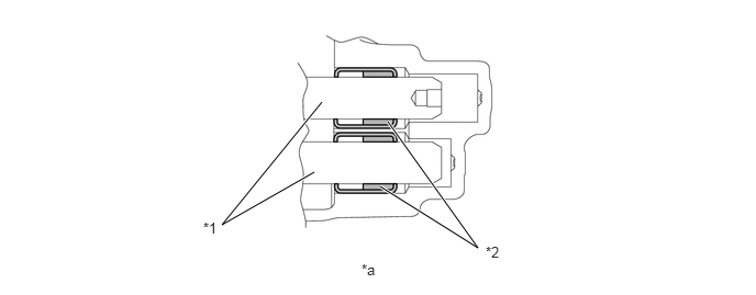
X108774E03
3.604,1.771 4.531,2.354 4.531,2.354 3.677,1.156 true 2.979,1.635 2.104,2.135 2.104,2.135 3.052,0.969 true 4.604,2.313 4.813,2.521 0.208,0.208 10 false *2 1.927,2.083 2.135,2.292 0.208,0.208 10 false *1 3.427,2.479 3.635,2.688 0.208,0.208 10 false *a

Text in Illustration
*1 Shift Fork Shaft *2 Slide Ball Bearing
*a Shift Fork Shaft Support Part - -


iv.

All shift forks in the shift fork shaft slide mechanism are fastened to the shift fork shaft, and a system whereby the entire fork shaft slides has been adopted, reducing friction during operation.
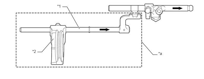
X108775E02
4.969,1.469 5.375,1.938 5.375,1.938 5.531,1.938 true 2.792,1.021 2.354,0.24 2.354,0.24 2.188,0.24 true 1.875,1.375 1.469,1.844 1.469,1.844 1.313,1.844 true 5.563,1.813 5.823,2.073 0.26,0.26 10 false *a 2.01,0.135 2.198,0.365 0.188,0.229 10 false *1 1.135,1.74 1.313,1.99 0.177,0.25 10 false *2

Text in Illustration
*1 Shift Fork Shaft *2 Shift Fork
*a The entire fork shaft slides smoothly. - -
V100135

Slide - -


v.

A ball plunger shift detent has been adopted for the shift detent mechanism, and a non-linear cam that enables quick select operation through negative slope characteristics and by clarifying the neutral gear position has been adopted.
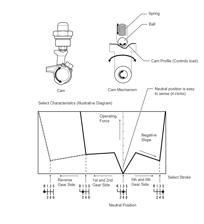
X135850E02
4.344,1.063 4.969,0.49 4.969,0.49 5.156,0.49 true 4.365,1.427 4.99,0.854 4.99,0.854 5.177,0.854 true 4.521,1.604 5.052,2.135 5.052,2.135 5.26,2.135 true 4.323,5.865 5.188,3.115 5.188,3.115 5.375,3.115 true 3.792,3.063 4.885,3.427 1.094,0.365 10 false Cam Mechanism 2,3.094 2.427,3.51 0.427,0.417 10 false Cam 5.219,0.385 5.75,0.75 0.531,0.365 10 false Spring 5.229,0.76 5.76,1.125 0.531,0.365 10 false Ball 5.313,2.052 7.052,2.552 1.74,0.5 10 false Cam Profile (Controls load) 5.438,3.031 6.906,3.844 1.469,0.813 10 false Neutral position is easy to sense (it clicks) 1.344,3.531 4,3.896 2.656,0.365 10 false Select Characteristics (Illustrative Diagram) 3.5,3.99 4.156,4.719 0.656,0.729 10 false Operating Force 4.969,4.656 5.531,5.292 0.563,0.635 10 false Negative Slope 5.896,6.135 6.813,6.469 0.917,0.333 10 false Select Stroke 4.615,6.219 5.354,7.063 0.74,0.844 10 false 5th and 6th Gear Side 3.25,6.24 3.99,7.052 0.74,0.813 10 false 1st and 2nd Gear Side 2.031,6.229 2.729,7.021 0.698,0.792 10 false Reverse Gear Side 3.833,7.115 4.958,7.594 1.125,0.479 10 false Neutral Position