Home › Vehicle Interior › SUPPLEMENTAL RESTRAINT SYSTEMS › AIRBAG SYSTEM › from 2016.06
NM2090E _58 Vehicle Interior _060650 SUPPLEMENTAL RESTRAINT SYSTEMS _0297353 AIRBAG SYSTEM UN GENERAL/CONTROL/DETAILS F

SUPPLEMENTAL RESTRAINT SYSTEMS  AIRBAG SYSTEM  GENERAL/CONTROL/DETAILS  DETAILS  


FUNCTION OF MAIN COMPONENTS


a.

The airbag system mainly consists of the parts listed in the table below.

Components Outline
Airbag Mainly consists of an inflator and a bag. Upon receiving a deployment signal from the airbag ECU assembly, the inflator generates gas to deploy the bag.
Front Seat Outer Belt Assembly Mainly consists of an inflator and a seat belt. Upon receiving a deployment signal from the airbag ECU assembly, the inflator generates gas to retract the seat belt.
Airbag Sensor Detects the deceleration of the vehicle during a collision, and transmits the signal to the airbag ECU assembly, from which the airbag ECU assembly determines whether ignition is necessary.
Airbag Cut Off Switch Cylinder Sub-assembly*1 Transmits on/off signals to the airbag ECU assembly to manually turn on or off the deployment of the instrument panel passenger without door airbag assembly.
Airbag ECU Assembly
·

Detects the deceleration of the vehicle during a collision, determines whether ignition is necessary based on the signals from each airbag sensor, and transmits deployment signals to each airbag and seat belt pretensioner.

·

The internal roll rate sensor detects vehicle tilt and roll speed. If the decision circuit determines a vehicle roll-over based on the detected roll angle signal and roll speed signal, deployment signals are transmitted to the curtain shield airbags and seat belt pretensioners.*2

·

Provides initial check and diagnosis function.


Combination Meter Assembly SRS Warning Light Turns on to alert the driver when the airbag ECU assembly detects a malfunction in the airbag system.
Master Warning Light*3 Turns on to alert the driver when the airbag ECU assembly detects a malfunction in the system.
Multi-information Display*3 Displays a warning message to inform the driver of a malfunction in the system.
Buzzer*3 Sounds to warn the driver of a malfunction in the system.
Clock Assembly Illuminates the Airbag ON indicator light and the Airbag OFF indicator light.*1

HINT:

*1: Models with passenger airbag cut off system

*2: Models for Korea

*3: Models with TFT LCD type multi-information display


OPERATING CONDITION


a.

Ignition Condition

i.

Deceleration sensors used for the airbag system are installed on various parts on the vehicle and transmit the deceleration data of each part during a collision.


ii.

Depending on the situation, the airbag ECU assembly sends a deployment signal to each airbag based on the information from each sensor.


iii.

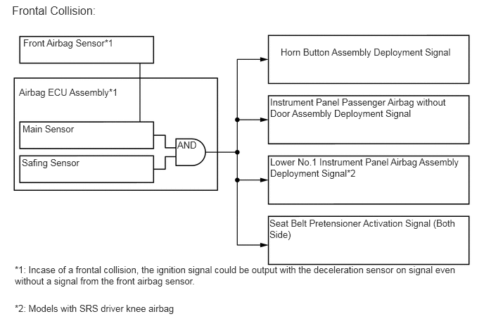
Frontal collision signals are produced based on the information from the airbag ECU assembly and the front airbag sensor. The frontal collision signals are used to deploy the horn button assembly, instrument panel passenger airbag without door assembly, lower No.1 instrument panel airbag assembly* and to activate the seat belt pretensioners.

HINT:

*: Models with SRS driver knee airbag


Y111934E08
0.344,0.552 2.021,0.917 1.677,0.365 10 false Front Airbag Sensor*1 0.177,0.052 1.688,0.5 1.51,0.448 12 false Frontal Collision: 0.281,1.281 2.031,1.646 1.75,0.365 10 false Airbag ECU Assembly*1 2.625,2.063 2.938,2.427 0.313,0.365 10 false AND 0.333,1.823 1.573,2.146 1.24,0.323 10 false Main Sensor 0.323,2.323 1.708,2.667 1.385,0.344 10 false Safing Sensor 0.219,3.906 6.958,4.49 6.74,0.583 10 false *1: Incase of a frontal collision, the ignition signal could be output with the deceleration sensor on signal even without a signal from the front airbag sensor. 0.219,4.479 2.76,4.802 2.542,0.323 10 false *2: Models with SRS driver knee airbag 4.156,0.688 6.792,1.104 2.635,0.417 10 false Horn Button Assembly Deployment Signal 4,1.427 6.906,2.094 2.906,0.667 10 false Instrument Panel Passenger Airbag without Door Assembly Deployment Signal 4,2.313 6.906,2.99 2.906,0.677 10 false Lower No.1 Instrument Panel Airbag Assembly Deployment Signal*2 3.99,3.219 6.875,3.875 2.885,0.656 10 false Seat Belt Pretensioner Activation Signal (Both Side)


iv.

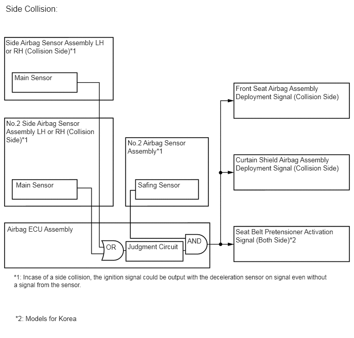
Side collision signals are produced based on the information from the side airbag sensor assembly or No.2 side airbag sensor assembly and No.2 airbag sensor assembly. Side collision signals are used to deploy the front seat airbag assembly, curtain shield airbag assembly and to activate the seat belt pretensioner*.

HINT:

*: Models for Korea


Y118998E05
0.115,0.073 2.198,0.542 2.083,0.469 12 false Side Collision: 0.115,0.781 2.208,1.438 2.094,0.656 10 false Side Airbag Sensor Assembly LH or RH (Collision Side)*1 4.771,1.708 7.021,2.354 2.25,0.646 10 false Front Seat Airbag Assembly Deployment Signal (Collision Side) 4.771,3.156 6.99,3.813 2.219,0.656 10 false Curtain Shield Airbag Assembly Deployment Signal (Collision Side) 4.771,4.615 6.99,5.26 2.219,0.646 10 false Seat Belt Pretensioner Activation Signal (Both Side)*2 0.125,2.417 1.969,3.594 1.844,1.177 10 false No.2 Side Airbag Sensor Assembly LH or RH (Collision Side)*1 0.292,1.49 1.49,1.844 1.198,0.354 10 false Main Sensor 0.323,3.667 1.438,3.99 1.115,0.323 10 false Main Sensor 2.792,3.667 3.969,4 1.177,0.333 10 false Safing Sensor 0.146,4.563 1.719,4.979 1.573,0.417 10 false Airbag ECU Assembly 0.281,5.542 6.865,6.271 6.583,0.729 9 false *1: Incase of a side collision, the ignition signal could be output with the deceleration sensor on signal even without a signal from the sensor. 2.583,4.917 3.667,5.271 1.083,0.354 10 false Judgment Circuit 2.583,2.813 4.156,3.594 1.573,0.781 10 false No.2 Airbag Sensor Assembly*1 2.146,4.927 2.438,5.188 0.292,0.26 10 false OR 3.792,4.802 4.146,5.125 0.354,0.323 10 false AND 0.313,6.375 1.885,6.813 1.573,0.438 10 false *2: Models for Korea


v.

Side rear collision signals are produced based on the information from the No.2 airbag sensor assembly and rear airbag sensor assembly. Side rear collision signals are used to deploy the curtain shield airbag assembly.
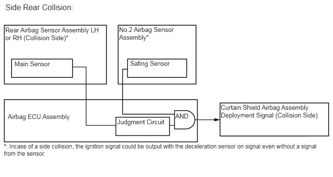
Y120056E05
0.115,0.052 2.167,0.51 2.052,0.458 12 false Side Rear Collision: 0.115,0.563 2.229,1.24 2.115,0.677 10 false Rear Airbag Sensor Assembly LH or RH (Collision Side)* 4.75,2.229 7.031,2.896 2.281,0.667 10 false Curtain Shield Airbag Assembly Deployment Signal (Collision Side) 0.313,1.292 1.469,1.635 1.156,0.344 10 false Main Sensor 2.802,1.281 3.927,1.625 1.125,0.344 10 false Safing Sensor 0.167,2.427 1.74,2.802 1.573,0.375 10 false Airbag ECU Assembly 0.083,3.073 7.073,3.771 6.99,0.698 9 false *: Incase of a side collision, the ignition signal could be output with the deceleration sensor on signal even without a signal from the sensor. 2.521,2.542 3.604,2.896 1.083,0.354 10 false Judgment Circuit 2.563,0.552 4.198,1.25 1.635,0.698 10 false No.2 Airbag Sensor Assembly* 3.771,2.417 4.135,2.688 0.365,0.271 10 false AND


vi.

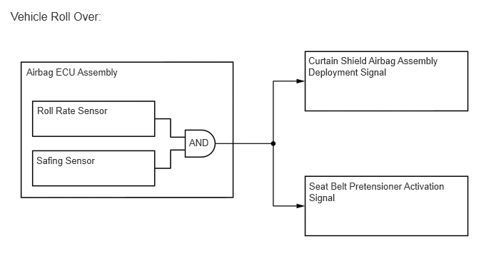
In case of a roll over, the airbag ECU assembly determines whether curtain shield airbag assembly deployment and seat belt pretensioner activation is necessary based on signals from the safing sensor and roll rate sensor. If the safing sensor and roll rate sensor turn on simultaneously, current flows to the squibs to deploy the SRS components as shown in the illustration below.*

HINT:

*: Models for Korea


Y201840E01
0.385,0.969 3.313,1.385 2.927,0.417 10 false Airbag ECU Assembly 0.156,0.135 3.375,0.688 3.219,0.552 12 false Vehicle Roll Over: 0.542,1.531 2.208,1.917 1.667,0.385 10 false Roll Rate Sensor 0.531,2.26 2.198,2.646 1.667,0.385 10 false Safing Sensor 4.51,2.635 6.75,3.385 2.24,0.75 10 false Seat Belt Pretensioner Activation Signal 4.5,0.802 6.76,1.552 2.26,0.75 10 false Curtain Shield Airbag Assembly Deployment Signal 2.76,2 3.115,2.25 0.354,0.25 10 false AND


SYSTEM CONTROL


a.

Airbag for Frontal Collision

i.

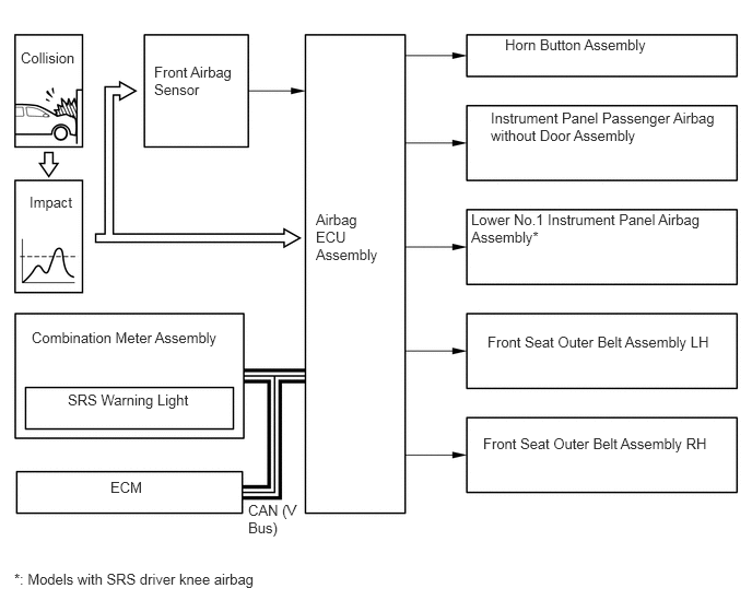
For frontal collisions, there are 3 airbags and 2 seat belt pretensioners: a horn button assembly, instrument panel passenger airbag without door assembly, lower No.1 instrument panel airbag assembly*, front seat outer belt assembly LH and front seat outer belt assembly RH. The deployment of the airbags and the activation of the seat belt pretensioners occur simultaneously.

HINT:

*: Models with SRS driver knee airbag


Y111984E08
1.469,0.604 2.323,1.167 0.854,0.563 10 false Front Airbag Sensor 0.198,0.469 0.781,0.833 0.583,0.365 10 false Collision 0.281,1.844 0.792,2.271 0.51,0.427 10 false Impact 3.01,2.01 3.688,3.344 0.677,1.333 10 false Airbag ECU Assembly 4.813,0.344 6.625,0.708 1.813,0.365 10 false Horn Button Assembly 4.677,1.042 6.875,1.688 2.198,0.646 10 false Instrument Panel Passenger Airbag without Door Assembly 4.49,2.01 6.938,2.688 2.448,0.677 10 false Lower No.1 Instrument Panel Airbag Assembly* 4.646,3.177 6.948,3.719 2.302,0.542 10 false Front Seat Outer Belt Assembly LH 4.604,4.146 6.948,4.667 2.344,0.521 10 false Front Seat Outer Belt Assembly RH 0.302,3.135 2.271,3.531 1.969,0.396 10 false Combination Meter Assembly 1.052,4.563 1.802,4.781 0.75,0.219 10 false ECM 2.365,4.781 2.875,5.417 0.51,0.635 10 false CAN (V Bus) 0.646,3.729 2.271,4.083 1.625,0.354 10 false SRS Warning Light 0.135,5.438 2.615,5.813 2.479,0.375 10 false *: Models with SRS driver knee airbag


b.

Airbag for Side Collision

i.

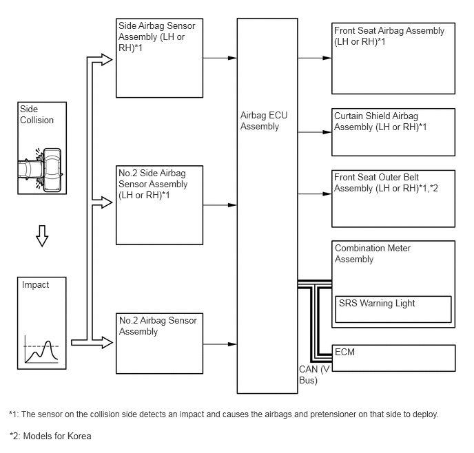
For a side collision, if the side airbag sensor assembly, No.2 side airbag sensor assembly, No.2 airbag sensor assembly detect an impact, it inform the airbag ECU assembly, and the airbag ECU assembly causes the front seat airbag assembly, curtain shield airbag assembly and seat belt pretensioner* to be deployed and operated simultaneously.

HINT:

*: Models for Korea


Y124254E04
5.052,0.375 6.792,1.385 1.74,1.01 10 false Front Seat Airbag Assembly (LH or RH)*1 5.052,1.667 6.771,2.323 1.719,0.656 10 false Curtain Shield Airbag Assembly (LH or RH)*1 5.052,2.594 6.792,3.406 1.74,0.813 10 false Front Seat Outer Belt Assembly (LH or RH)*1,*2 5.063,3.667 6.656,4.458 1.594,0.792 10 false Combination Meter Assembly 5.125,4.5 6.771,4.844 1.646,0.344 10 false SRS Warning Light 5.063,5.24 5.792,5.583 0.729,0.344 10 false ECM 4.521,5.5 5,6.208 0.479,0.708 10 false CAN (V Bus) 1.792,0.302 2.99,1.448 1.198,1.146 10 false Side Airbag Sensor Assembly (LH or RH)*1 1.792,2.531 3.021,3.667 1.229,1.135 10 false No.2 Side Airbag Sensor Assembly (LH or RH)*1 1.802,4.76 3.01,5.615 1.208,0.854 10 false No.2 Airbag Sensor Assembly 0.302,1.563 0.948,2.229 0.646,0.667 10 false Side Collision 0.333,4.219 0.927,4.625 0.594,0.406 10 false Impact 0.135,6.188 6.979,6.521 6.844,0.333 9 false *1: The sensor on the collision side detects an impact and causes the airbags and pretensioner on that side to deploy. 3.635,1.656 4.375,2.635 0.74,0.979 10 false Airbag ECU Assembly 0.146,6.51 1.583,6.833 1.438,0.323 10 false *2: Models for Korea


c.

Airbag for Side Rear Collision

i.

For a side rear collision, if the rear airbag sensor assembly, No.2 airbag sensor assembly detect an impact, it inform the airbag ECU assembly, and the airbag ECU assembly causes the curtain shield airbag assembly to be deployed and operated simultaneously.
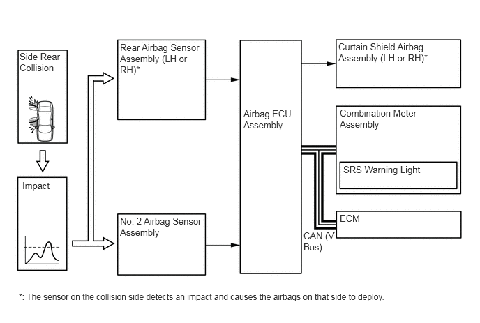
Y124255E03
5.052,0.615 6.76,1.271 1.708,0.656 10 false Curtain Shield Airbag Assembly (LH or RH)* 5.073,1.604 6.688,2.396 1.615,0.792 10 false Combination Meter Assembly 5.125,2.448 6.771,2.771 1.646,0.323 10 false SRS Warning Light 5.073,3.177 5.802,3.5 0.729,0.323 10 false ECM 4.531,3.438 5,4.281 0.469,0.844 10 false CAN (V Bus) 1.792,0.625 3.021,1.74 1.229,1.115 10 false Rear Airbag Sensor Assembly (LH or RH)* 1.792,3.219 3.021,4.063 1.229,0.844 10 false No. 2 Airbag Sensor Assembly 0.292,0.76 0.958,1.438 0.667,0.677 10 false Side Rear Collision 0.333,2.688 0.927,3.198 0.594,0.51 10 false Impact 0.281,4.354 6.677,4.74 6.396,0.385 9 false *: The sensor on the collision side detects an impact and causes the airbags on that side to deploy. 3.635,1.615 4.396,2.573 0.76,0.958 10 false Airbag ECU Assembly


d.

Airbag for Roll Over (Models for Korea)

i.

If the vehicle is tilted and rolls over, the airbag ECU assembly activates the curtain shield airbag assemblies and the seat belt pretensioners for the driver and front passenger based on signals that show the vehicle's roll angle and rotation speed.
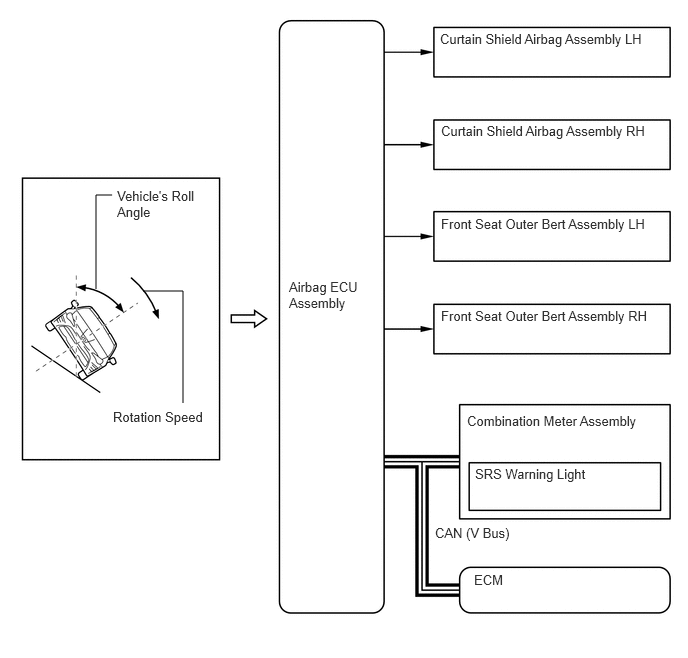
Y202425E01
1,3.01 1,2.031 1,2.031 1.167,2.031 false 1.906,4.198 1.906,3.031 1.906,3.031 1.49,3.031 false 3.01,2.906 3.875,4.188 0.865,1.281 10 false Airbag ECU Assembly 4.865,4.302 6.906,4.719 2.042,0.417 10 false Combination Meter Assembly 4.948,4.854 6.823,5.24 1.875,0.385 10 false SRS Warning Light 4.938,5.958 6.792,6.313 1.854,0.354 10 false ECM 4.531,5.469 6.469,5.833 1.938,0.365 10 false CAN (V Bus) 1.219,1.958 2.177,2.76 0.958,0.802 10 false Vehicle's Roll Angle 1.177,4.26 2.177,4.729 1,0.469 10 false Rotation Speed 4.594,3.208 6.885,3.646 2.292,0.438 10 false Front Seat Outer Bert Assembly RH 4.594,2.25 6.885,2.688 2.292,0.438 10 false Front Seat Outer Bert Assembly LH 4.594,1.281 6.885,1.719 2.292,0.438 10 false Curtain Shield Airbag Assembly RH 4.583,0.323 6.875,0.76 2.292,0.438 10 false Curtain Shield Airbag Assembly LH


ii.

If the vehicle rolls over in a side collision, the airbag ECU assembly causes the front seat airbag assembly and curtain shield airbag assembly to deploy based on signals from the side airbag sensor assembly, No. 2 side airbag sensor assembly and No. 2 airbag sensor assembly. Meanwhile, it activates the curtain shield airbag assembly on the opposite side of the collision and the seat belt pretensioners for the driver and front passenger, based on lateral deceleration signal, rotation speed signal and roll angle signal.
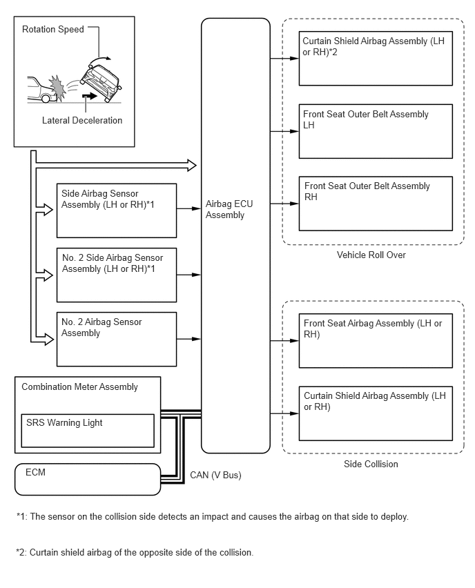
Y202426E01
1.49,0.865 1.49,0.406 1.49,0.406 1.323,0.406 false 1.292,1.698 1.292,1.448 true 4.563,0.531 6.74,1.229 2.177,0.698 10 false Curtain Shield Airbag Assembly (LH or RH)*2 4.573,1.635 6.698,2.323 2.125,0.688 10 false Front Seat Outer Belt Assembly LH 4.594,2.719 6.719,3.406 2.125,0.688 10 false Front Seat Outer Belt Assembly RH 4.583,5.885 6.76,6.583 2.177,0.698 10 false Curtain Shield Airbag Assembly (LH or RH) 4.583,4.792 6.76,5.49 2.177,0.698 10 false Front Seat Airbag Assembly (LH or RH) 0.323,5.75 2.365,6.188 2.042,0.438 10 false Combination Meter Assembly 0.396,6.292 2.219,6.688 1.823,0.396 10 false SRS Warning Light 0.385,7.042 2.24,7.417 1.854,0.375 10 false ECM 2.865,7.083 4.125,7.469 1.26,0.385 10 false CAN (V Bus) 5.188,6.917 6.125,7.344 0.938,0.427 10 false Side Collision 5.083,3.76 6.427,4.229 1.344,0.469 10 false Vehicle Roll Over 3.104,2.99 3.979,4.229 0.875,1.24 10 false Airbag ECU Assembly 0.333,0.354 1.302,0.781 0.969,0.427 10 false Rotation Speed 0.635,1.729 1.927,2.115 1.292,0.385 10 false Lateral Deceleration 0.927,2.833 2.563,3.521 1.635,0.688 10 false Side Airbag Sensor Assembly (LH or RH)*1 0.938,3.802 2.573,4.5 1.635,0.698 10 false No. 2 Side Airbag Sensor Assembly (LH or RH)*1 0.25,7.708 6.656,8.125 6.406,0.417 10 false *1: The sensor on the collision side detects an impact and causes the airbag on that side to deploy. 0.24,8.25 6.625,8.635 6.385,0.385 10 false *2: Curtain shield airbag of the opposite side of the collision. 0.927,4.771 2.563,5.448 1.635,0.677 10 false No. 2 Airbag Sensor Assembly


e.

Primary Check Illumination Control

i.

After the ignition switch is turned ON, the airbag ECU assembly illuminates the SRS warning light in the combination meter assembly for approximately 6 seconds and conducts the primary check. During the primary check, the ignition of airbags is prohibited and a diagnosis of the airbag ECU assembly is performed. If trouble is detected during the primary check, the SRS warning light remains on even after the 6 seconds have elapsed. See the illustration below.
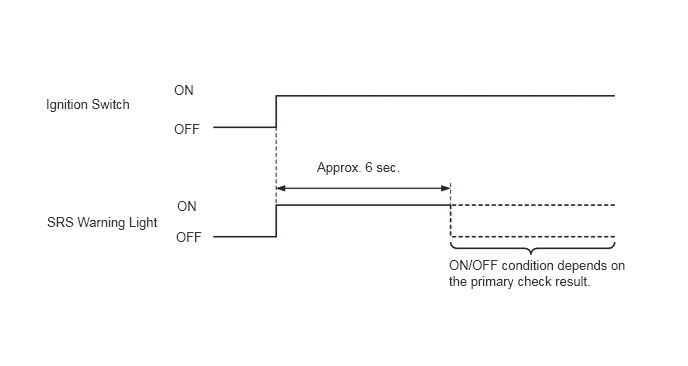
Y111985E10
0.479,1 1.396,1.438 0.917,0.438 10 false Ignition Switch 0.49,2.229 1.729,2.74 1.24,0.51 10 false SRS Warning Light 1.813,0.854 2.135,1.177 0.323,0.323 10 false ON 1.813,1.26 2.208,1.583 0.396,0.323 10 false OFF 1.844,2.063 2.167,2.385 0.323,0.323 10 false ON 1.833,2.385 2.229,2.708 0.396,0.323 10 false OFF 3.302,1.656 4.333,1.948 1.031,0.292 10 false Approx. 6 sec. 4.677,2.677 6.573,3.646 1.896,0.969 10 false ON/OFF condition depends on the primary check result.


ii.

After the ignition switch is turned ON, the airbag ECU assembly operates the airbag ON/OFF indicator lights as shown below to check for an open in the airbag cut off switch indicator circuit.*

HINT:

*: Models with passenger airbag cut off system
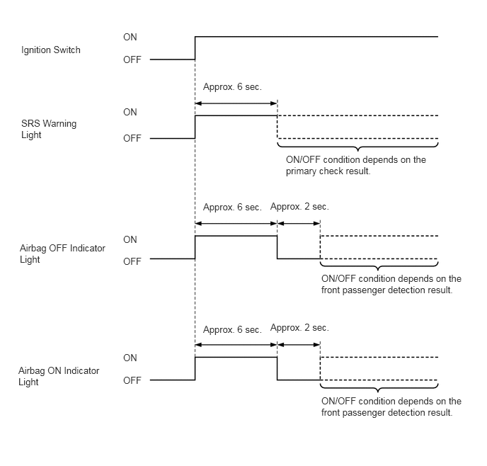

Y124256E03
1.813,0.458 2.115,0.781 0.302,0.323 10 false ON 0.313,0.646 1.552,0.969 1.24,0.323 10 false Ignition Switch 2.99,1.188 3.906,1.51 0.917,0.323 10 false Approx. 6 sec. 2.99,2.958 3.906,3.281 0.917,0.323 10 false Approx. 6 sec. 3.979,2.948 4.896,3.271 0.917,0.323 10 false Approx. 2 sec. 3.979,4.729 4.896,5.052 0.917,0.323 10 false Approx. 2 sec. 4.208,2.26 6.375,2.906 2.167,0.646 10 false ON/OFF condition depends on the primary check result. 4.729,4.01 6.99,4.813 2.26,0.802 10 false ON/OFF condition depends on the front passenger detection result. 4.729,5.813 6.938,6.656 2.208,0.844 10 false ON/OFF condition depends on the front passenger detection result. 2.99,4.76 3.906,5.083 0.917,0.323 10 false Approx. 6 sec. 1.813,0.792 2.115,1.115 0.302,0.323 10 false OFF 0.313,1.729 1.406,2.385 1.094,0.656 10 false SRS Warning Light 0.292,3.563 1.667,4.219 1.375,0.656 10 false Airbag OFF Indicator Light 0.271,5.365 1.531,6.021 1.26,0.656 10 false Airbag ON Indicator Light 1.813,1.563 2.115,1.885 0.302,0.323 10 false ON 1.813,1.948 2.115,2.271 0.302,0.323 10 false OFF 1.813,3.438 2.115,3.76 0.302,0.323 10 false ON 1.813,3.76 2.115,4.083 0.302,0.323 10 false OFF 1.813,5.177 2.115,5.5 0.302,0.323 10 false ON 1.813,5.51 2.115,5.833 0.302,0.323 10 false OFF


FUNCTION


a.

Airbag Cut Off Switch Cylinder Sub-assembly

i.

The deployment of the instrument panel passenger airbag without door assembly can be prohibited by operating the airbag cut off switch cylinder sub-assembly located on the side portion of the instrument panel on the front passenger side. When the airbag cut off switch cylinder sub-assembly is turned to off, airbag will not be deployed even if a collision occurs.


ii.

Turn the airbag cut off switch cylinder sub-assembly on and off by inserting the key and turning it.


iii.

The airbag ON/OFF indicator lights, which inform the driver of the airbag cut off switch status, have been provided in the clock assembly.


iv.

The table below shows whether the airbags for the front passenger are enabled or disabled and the airbag ON/OFF indicator lights come on or go off depending on the airbag cut off switch status.

Item Airbag Cut Off Switch Cylinder Sub-assembly Condition
ON OFF Malfunction
Instrument Panel Passenger Airbag without Door Assembly ○ - -
Front Seat Airbag Assembly ○ ○ ○
Front Seat Outer Belt Assembly ○ ○ ○
Airbag ON Indicator Light ○ - -
Airbag OFF Indicator Light - ○ ○

HINT:

○: Enabled (Light comes on)

-: Disabled (Light goes off)


CONSTRUCTION


a.

Dual-stage SRS Airbags

i.

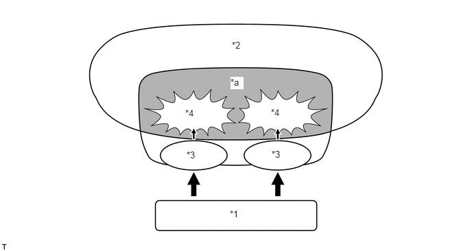
To support the dual-stage control, these airbag assemblies contain 2 sets of initiators and propellants. The airbag ECU assembly helps optimize the airbag inflation output by delaying the inflation timing of these initiators.*

HINT:

*: Models for Korea


Y112390E02
3.49,3.167 3.771,3.375 0.281,0.208 10 false *1 3.521,0.604 3.781,0.844 0.26,0.24 10 false *2 3.5,1.167 3.698,1.354 0.198,0.188 10 true *a 2.813,1.635 3.042,1.854 0.229,0.219 10 false *4 2.833,2.271 3.073,2.479 0.24,0.208 10 false *3 4.115,1.625 4.375,1.844 0.26,0.219 10 false *4 4.125,2.26 4.365,2.479 0.24,0.219 10 false *3

Text in Illustration
*1 Airbag ECU Assembly *2 Bag
*3 Initiator *4 Propellant
*a Compressive Gas - -


b.

Horn Button Assembly and Instrument Panel Passenger Airbag without Door Assembly

i.

The horn button assembly and instrument panel passenger airbag without door assembly mainly consist of an inflator and a bag.


c.

Lower No.1 Instrument Panel Airbag Assembly

i.

The lower No.1 instrument panel airbag assembly consists of an airbag door, an inflator and a bag.*

HINT:

*: Models with SRS driver knee airbag


d.

Front Seat Airbag Assembly

i.

Front seat airbag assemblies are installed in the seat backs of the driver seat and the front passenger seat. Each front seat airbag assembly consists of an inflator, a bag and a retainer.


e.

Curtain Shield Airbag Assembly

i.

Curtain shield airbag assemblies that extend from the front pillar to the roof side rail are installed. Each curtain shield airbag assembly consists of an inflator and a bag.


f.

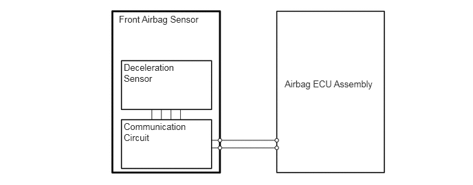
Front Airbag Sensor

i.

A deceleration sensor is enclosed in the front airbag sensor. Based on the deceleration of the vehicle during a front collision, a distortion is created in the sensor and converted into an electrical signal.
Y111919E05
4.313,1.188 5.813,1.698 1.5,0.51 10 false Airbag ECU Assembly 1.802,0.208 3.24,0.708 1.438,0.5 10 false Front Airbag Sensor 1.875,0.938 2.927,1.625 1.052,0.688 10 false Deceleration Sensor 1.875,1.833 3.156,2.531 1.281,0.698 10 false Communication Circuit


g.

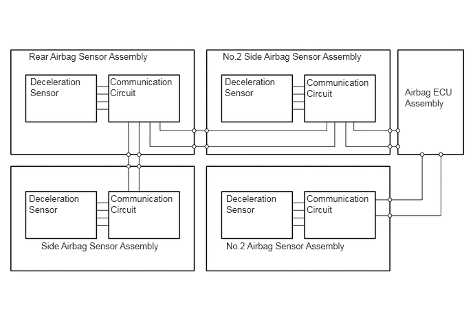
Side Airbag Sensor Assembly, No.2 Side Airbag Sensor Assembly, Rear Airbag Sensor Assembly and No.2 Airbag Sensor Assembly

i.

A deceleration sensor is enclosed in the side airbag sensor assembly, No.2 side airbag sensor assembly, rear airbag sensor assembly and No.2 airbag sensor assembly. Based on the deceleration of the vehicle during a side collision, a distortion is created in the sensor and converted into an electrical signal.
Y119001E02
6.135,1.313 6.938,2.229 0.802,0.917 10 false Airbag ECU Assembly 0.625,3.646 2.823,4.021 2.198,0.375 10 false Side Airbag Sensor Assembly 0.438,0.771 2.875,1.104 2.438,0.333 10 false Rear Airbag Sensor Assembly 3.375,0.771 5.833,1.104 2.458,0.333 10 false No.2 Side Airbag Sensor Assembly 3.427,3.646 5.802,3.99 2.375,0.344 10 false No.2 Airbag Sensor Assembly 0.438,2.927 1.354,3.583 0.917,0.656 10 false Deceleration Sensor 1.677,2.927 2.677,3.583 1,0.656 10 false Communication Circuit 0.458,1.156 1.385,1.823 0.927,0.667 10 false Deceleration Sensor 1.667,1.156 2.677,1.813 1.01,0.656 10 false Communication Circuit 3.406,1.156 4.333,1.823 0.927,0.667 10 false Deceleration Sensor 4.646,1.167 5.646,1.813 1,0.646 10 false Communication Circuit 3.427,2.927 4.344,3.583 0.917,0.656 10 false Deceleration Sensor 4.646,2.927 5.635,3.583 0.99,0.656 10 false Communication Circuit


h.

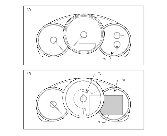
Combination Meter

i.

When a system malfunction is detected, the system illuminates the SRS warning light and master warning light*, sounds a buzzer* and displays a warning message on the multi-information display* to warn the driver.

HINT:

*: Models with TFT LCD type multi-information display

Y202578E02
4.802,2.313 4.729,2.531 4.729,2.531 4.573,2.531 true 4.677,4.896 4.521,5.25 4.521,5.25 4.365,5.25 true 4.917,3.854 5.052,3.438 5.052,3.438 5.198,3.438 true 3.74,3.896 4.052,3.177 4.052,3.177 4.198,3.177 true 1.156,0.302 1.427,0.521 0.271,0.219 12 false *A 4.406,2.438 4.625,2.656 0.219,0.219 10 false *a 1.156,3.063 1.427,3.281 0.271,0.219 12 false *B 4.198,5.146 4.417,5.365 0.219,0.219 10 false *c 5.24,3.333 5.458,3.552 0.219,0.219 10 false *a 4.219,3.063 4.438,3.281 0.219,0.219 10 false *b

Text in Illustration
*A Models with Segment LCD type multi-information display *B Models with TFT LCD type multi-information display
*a SRS Warning Light *b Master Warning Light
*c Multi-information Display - -

Detail SRS Warning Light Master Warning Light* Multi-information Display* Buzzer*
System Malfunction in Airbag System Illuminates Illuminates Check SRS Airbag System Sounds Once

HINT:

*: Models with TFT LCD type multi-information display


DIAGNOSIS


a.

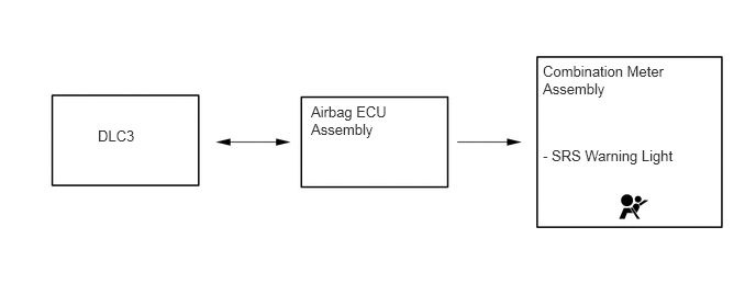
If the airbag ECU assembly detects a malfunction in the airbag system, the airbag ECU assembly stores the malfunction data in memory, in addition to illuminating the SRS warning light.


b.

The DTC can be read by connecting the Grobal TechStream (GTS) to DLC3.


c.

If the SRS airbag deploys, the airbag ECU assembly will turn on the SRS warning light. Then, an "ignition record code" will be recorded as a DTC. The SRS warning light cannot be turned off. It is necessary to replace the airbag ECU assembly with a new one.
Y100869E08
2.948,0.979 4.104,1.74 1.156,0.76 10 false Airbag ECU Assembly 0.927,1.208 1.417,1.594 0.49,0.385 10 false DLC3 5.146,0.594 6.74,1.354 1.594,0.76 10 false Combination Meter Assembly 5.146,1.396 6.719,1.76 1.573,0.365 10 false - SRS Warning Light