FA20 EMISSION CONTROL CANISTER INSPECTION
PROCEDURE

 77740
1.INSPECT CHARCOAL CANISTER ASSEMBLY (for Metal Type)
- NOTICE:
-
When applying vacuum, the needle may waver but, as long as the needle returns to its initial position immediately, it is not a malfunction.
Visually check the charcoal canister assembly for cracks or damage.
If cracks or damage is found, replace the charcoal canister assembly.
Check the air flow.
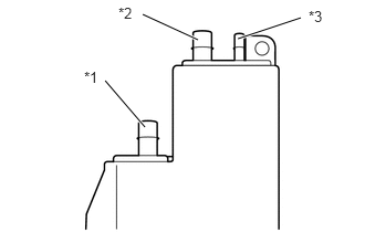
Using a vacuum pump, check the air flow according to the procedures below.
| *1 | Port A |
| *2 | Port B |
| *3 | Port C |
- OK:
Measurement Condition Specified Condition Ports B and C closed, and vacuum applied to port A (2 kPa (15 mmHg, 0.590 in.Hg)) No air leaks Port C closed, and vacuum applied to port A (2 kPa (15 mmHg, 0.590 in.Hg)) Air flows from port B Port C closed and air blown into port A (5 kPa (0.1 kgf/cm2, 0.725 psi)) Air flows from port B Air blown into port A (5 kPa (0.1 kgf/cm2, 0.725 psi)) Air flows from ports B and C
If the result is not as specified, replace the charcoal canister assembly.
2.INSPECT CHARCOAL CANISTER ASSEMBLY (for Clamp Type)
- NOTICE:
-
When applying vacuum, the needle may waver but, as long as the needle returns to its initial position immediately, it is not a malfunction.
Visually check the charcoal canister assembly for cracks or damage.
If cracks or damage is found, replace the charcoal canister assembly.
Check the air flow.
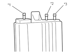
Using a vacuum pump, check the air flow according to the procedures below.
| *1 | Port A |
| *2 | Port B |
| *3 | Port C |
- OK:
Measurement Condition Specified Condition Ports B and C closed, and vacuum applied to port A (2 kPa (15 mmHg, 0.590 in.Hg)) No air leaks Port C closed, and vacuum applied to port A (2 kPa (15 mmHg, 0.590 in.Hg)) Air flows from port B Port C closed and air blown into port A (5 kPa (0.1 kgf/cm2, 0.725 psi)) Air flows from port B Air blown into port A (5 kPa (0.1 kgf/cm2, 0.725 psi)) Air flows from ports B and C
If the result is not as specified, replace the charcoal canister assembly.
77740S
3.INSPECT CANISTER PUMP MODULE (for Metal Type)
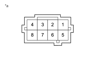
Measure the resistance according to the value in the table below.
- Standard Resistance:
Tester Connection Condition Specified Condition 1 - 5 20°C (68°F) 25 to 30 Ω 1 - 5 60°C (140°F) 27 to 35 Ω
| *a | Component without harness connected
(Canister Pump Module) |
Check the operation of the check valve.
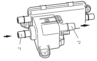
Install a clean hose to the purge valve.
Check that air flows from port A to port B.
| *1 | Port A |
| *2 | Port B |
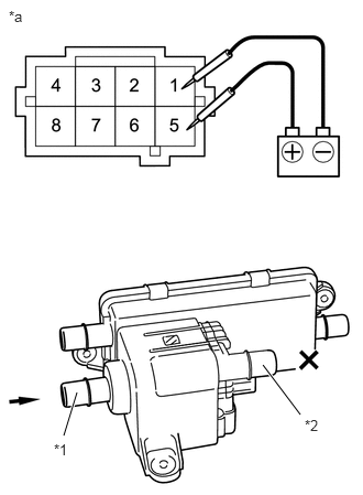
Connect the positive (+) lead of the battery to terminal 5 and the negative (-) lead to terminal 1.
Check that air does not flow from port A to port B.
| *1 | Port A |
| *2 | Port B |
| *a | Component without harness connected
(Canister Pump Module) |
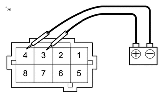
Connect the positive (+) lead of the battery to terminal 3 and the negative (-) lead to terminal 4.
| *a | Component without harness connected
(Canister Pump Module) |
Check that the vacuum pump operates.
- NOTICE:
-
Do not operate vacuum pump for 5 minutes or more.
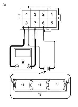
Connect the positive (+) lead of the battery to terminal 6 and the negative (-) lead to terminal 8.
| *1 | 1.5 V |
| *2 | 4.8 to 5.2 V |
| *a | Component without harness connected
(Canister Pump Module) |
Measure the voltage according to the value in the table below.
- Standard Voltage:
Tester Connection Condition Specified Condition 7 - 8 25°C (77°F) 3.5 V
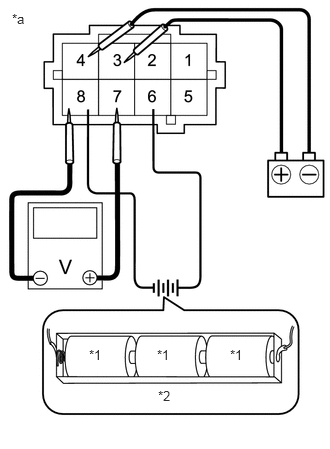
Connect the positive (+) lead of the battery to terminal 6 and the negative (-) lead to terminal 8.
| *1 | 1.5 V |
| *2 | 4.8 to 5.2 V |
| *a | Component without harness connected
(Canister Pump Module) |
Connect the positive (+) lead of the battery to terminal 3 and the negative (-) lead to terminal 4. Check that the voltage drops slightly from 3.5 volts.