FA20 INTAKE / EXHAUST INTAKE MANIFOLD DISASSEMBLY
PROCEDURE

 89420M
1.REMOVE MANIFOLD ABSOLUTE PRESSURE SENSOR
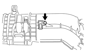
Remove the bolt and manifold absolute pressure sensor from the intake manifold.
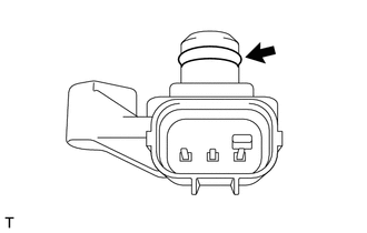
Remove the O-ring from the manifold absolute pressure sensor.
17650
2.REMOVE PURGE VALVE
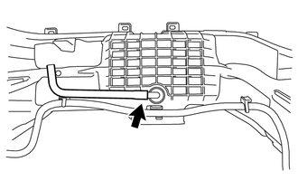
Disconnect the No. 1 fuel vapor feed hose from the intake manifold.
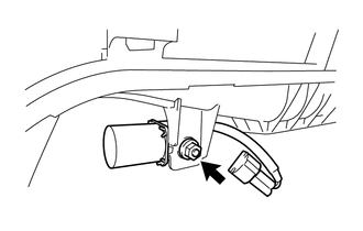
Remove the nut and purge valve.
55434E
3.REMOVE CAP (for Automatic Transmission)
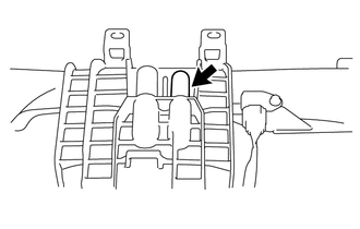
Remove the cap from the intake manifold.
4.REMOVE FUEL DELIVERY PIPE (for Bank 2)
Disconnect the No. 2 fuel delivery pipe sub-assembly from the fuel delivery pipe.
- NOTICE:
- ·
If the connector and pipe are stuck, pinch the fuel delivery pipe by hand and push and pull the connector to disconnect it
·Do not allow any scratches or foreign matter on the parts when disconnecting them, as the No. 2 fuel delivery pipe sub-assembly joint contains the O-rings that seal the plug.
·Do not use any tools to separate the pipe and connector.
·Do not forcibly bend, twist or turn the nylon tube.
·If the pipe and connector are stuck together, pinch the tube between your fingers and turn it carefully to free it. Then, disconnect the main tube.
·Protect the disconnected part by covering it with a plastic bag and tape after disconnecting the main tube.
·Check that the top hat cannot be pulled out.
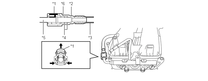
| *1 | Retainer | *2 | No. 2 Fuel Delivery Pipe Sub-assembly Connector |
| *3 | Nylon Tube | *4 | O-ring |
| *5 | fuel delivery pipe | *6 | Top Hat |
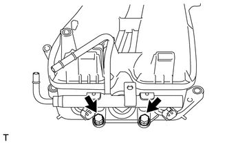
Remove the 2 bolts and the fuel delivery pipe from the intake manifold.
Remove the 2 O-rings.
5.REMOVE FUEL DELIVERY PIPE (for Bank 1)
- HINT:
-
Use the same procedure described for the fuel delivery pipe (for bank 2).
23808
6.REMOVE NO. 2 FUEL DELIVERY PIPE SUB-ASSEMBLY
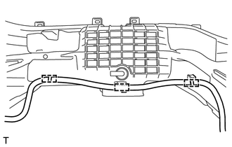
Disengage the 3 clamps and remove the No. 2 fuel delivery pipe sub-assembly from the intake manifold.