FA20 INTAKE / EXHAUST INTAKE MANIFOLD REASSEMBLY
PROCEDURE

 23808
1.INSTALL NO. 2 FUEL DELIVERY PIPE SUB-ASSEMBLY
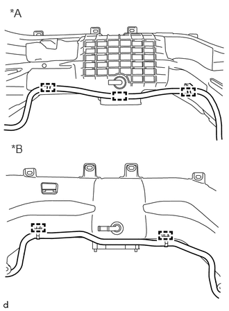
Install the No. 2 fuel delivery pipe sub-assembly to the intake manifold with the 3 clamps. (for resin intake manifold)
Install the No. 2 fuel delivery pipe sub-assembly to the intake manifold with the 2clamps. (for aluminum intake manifold)
| *A | for Resin Intake Manifold |
| *B | for Aluminum Intake Manifold |
2.INSTALL FUEL DELIVERY PIPE (for Bank 2)
Apply a gasoline to the contact surfaces of the new O-ring on each fuel injector assembly.
Install a new 2 O-rings to each fuel injector assembly.
Install the fuel injector assembly to the intake manifold with fuel delivery pipe.
- NOTICE:
- ·
Do not damage the fuel injector assembly or the O-ring.
·Do not twist the O-ring.
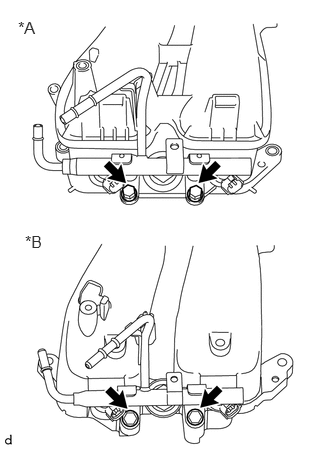
Install the fuel delivery pipe with the 2 bolts.
- Torque:
- 19 N*m (194 kgf*cm, 14 ft.*lbf)
| *A | for Resin Intake Manifold |
| *B | for Aluminum Intake Manifold |
Check that the fuel injectors rotate smoothly.
- NOTICE:
-
If the fuel injectors do not rotate smoothly, the probable cause is incorrect installation of the O-rings. Replace the O-rings.
Position the fuel injector connector outward.
3.INSTALL FUEL DELIVERY PIPE (for Bank 1)
- HINT:
-
Use the same procedure described for the fuel delivery pipe (for bank 2).
55434E
4.INSTALL CAP (for Automatic Transmission)
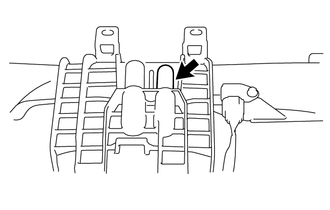
Install the cap to the intake manifold.
17650
5.INSTALL PURGE VALVE
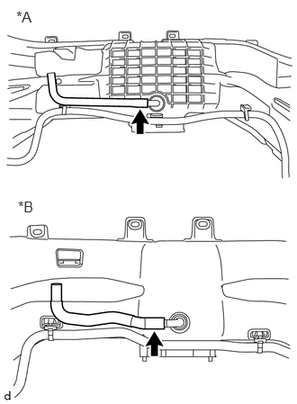
Connect the No. 1 fuel vapor feed hose to the intake manifold.
| *A | for Resin Intake Manifold |
| *B | for Aluminum Intake Manifold |
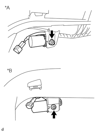
Install the nut and purge valve to the intake manifold.
- Torque:
- 6.4 N*m (65 kgf*cm, 57 in.*lbf)
| *A | for Resin Intake Manifold |
| *B | for Aluminum Intake Manifold |
89420M
6.INSTALL MANIFOLD ABSOLUTE PRESSURE SENSOR
Apply engine oil to the contact surfaces of the new O-ring on manifold absolute pressure sensor.
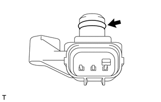
Install a new O-ring to the manifold absolute pressure sensor.
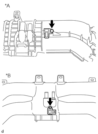
Install the manifold absolute pressure sensor to the intake manifold with the bolt.
- Torque:
- for Resin Intake Manifold : 4.0 N*m (41 kgf*cm, 35 in.*lbf)
- for Aluminum Intake Manifold : 3.4 N*m (35 kgf*cm, 30 in.*lbf)
| *A | for Resin Intake Manifold |
| *B | for Aluminum Intake Manifold |