FA20 STARTING STARTER(for Manual Transmission) REASSEMBLY
PROCEDURE

 28011
1.INSTALL STARTER CLUTCH SUB-ASSEMBLY
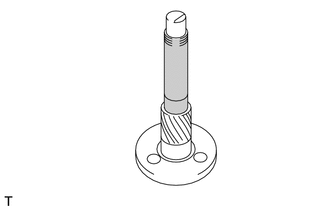
Apply high-temperature grease to the shaft as shown in the illustration.

|
High-temperature Grease |
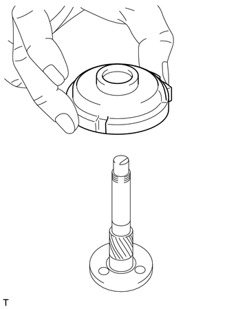
Install the internal gear to the shaft.
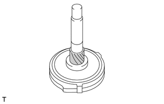
Apply high-temperature grease to the shaft as shown in the illustration.
|
|
High-temperature Grease |
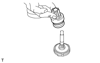
Install the over running clutch to the shaft.
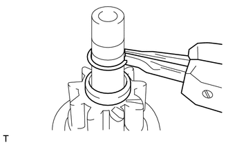
Install the stopper to the shaft.
Using snap ring pliers, install the snap ring.
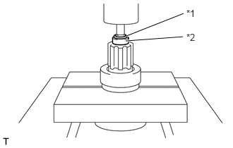
Using a press, press the snap ring into the stopper.
| *1 | Snap Ring |
| *2 | Stopper |
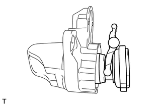
Install the starter clutch sub-assembly together with the drive lever set pin to the starter drive housing assembly.
2.INSTALL STARTER PLANETARY GEAR
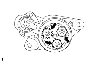
Apply high-temperature grease to the planetary gears and pins of the planetary shaft.
Install the 3 starter planetary gears.

|
High-temperature Grease |
3.INSTALL STARTER HOUSING RUBBER
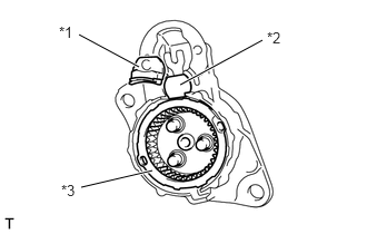
Install the starter housing rubber, seal rubber and plate to the starter drive housing assembly.
| *1 | Starter Housing Rubber |
| *2 | Plate |
| *3 | Seal Rubber |
28160
4.INSTALL STARTER ARMATURE ASSEMBLY
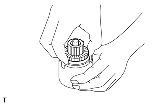
Install the starter armature assembly to the starter yoke assembly.
28120
5.INSTALL STARTER YOKE ASSEMBLY
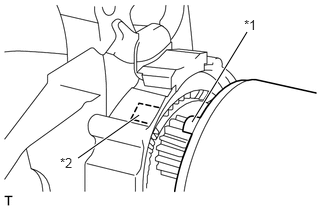
Align the claw of the starter yoke assembly with the groove inside the starter drive housing assembly.
| *1 | Claw |
| *2 | Groove |
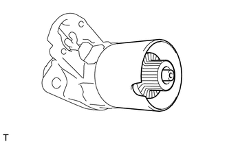
Install the starter yoke assembly together with the starter armature assembly to the starter drive housing assembly.
28140
6.INSTALL STARTER BRUSH HOLDER ASSEMBLY
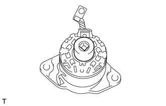
Install a 24 mm socket to the starter brush holder assembly.
Install the starter brush holder assembly to the starter armature assembly.
28199
7.INSTALL STARTER COVER
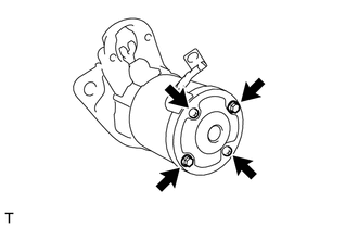
Install the starter cover with 2 screws and 2 bolts.
- Torque:
- Bolt : 6.0 N*m (61 kgf*cm, 53 in.*lbf)
- Screw : 1.4 N*m (14 kgf*cm, 12 in.*lbf)
28150
8.INSTALL MAGNET STARTER SWITCH ASSEMBLY
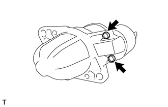
Install the magnet starter switch assembly with the 2 screws.
- Torque:
- 7.5 N*m (76 kgf*cm, 66 in.*lbf)
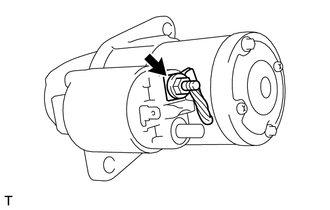
Connect the lead wire to terminal C with the nut.
- Torque:
- 10 N*m (102 kgf*cm, 7 ft.*lbf)