TX6A AUTOMATIC TRANSMISSION / TRANSAXLE AUTOMATIC TRANSMISSION SYSTEM P0882 TCM Power Input Signal Low
DESCRIPTION
TCM detects a reduction in power supply voltage, and depending on status, implements the following fail-safe.
Learning control prohibition (when detection conditions 1 or 2 are met)
Slip control, lock-up control, manual mode, shift paddle operation prohibition, torque up prohibition, and prohibition on shifting to 5th or 6th. If this continues further, power is cut to all solenoids (fixed to 4th).
| DTC Code | DTC Detection Condition
1.
Diagnosis Condition 2.
Malfunction Status 3.
Malfunction Time 4.
Other |
Trouble Area |
|---|---|---|
| P0882 | 1.
The engine speed and input speed sensor NT are 400 rpm or more, and the CAN communication and input speed NT are normal 2.
Ignition voltage is 9.0 V or less 3.
Continues for 20 sec. 4.
1-trip detection logic |
·
IG circuit ·
Harness and connector ·
TCM |
WIRING DIAGRAM
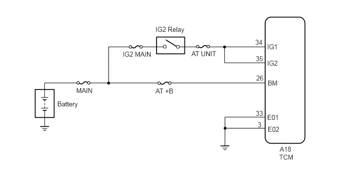
CAUTION / NOTICE / HINT
- NOTICE:
-
Inspect the fuses circuits related to this system before performing the following inspection procedure.
PROCEDURE
Disconnect the A18 TCM connector.
Measure the voltage according to the value(s) in the table below.
- Standard Voltage:
Tester Connection Condition Specified Condition A18-34(IG1) - Body ground Ignition switch ON 11 to 14 V A18-35(IG2) - Body ground Ignition switch ON 11 to 14 V
Measure the resistance according to the value(s) in the table below.
- Standard Resistance:
Tester Connection Condition Specified Condition A18-3(E02) - Body ground Always Below 1 Ω A18-33(E01) - Body ground Always Below 1 Ω
Connect the A18 TCM connector.
OK
NG
Replace the TCM (See page Drivetrain>TX6A (AUTOMATIC TRANSMISSION / TRANSAXLE)>TCM>REMOVAL).
NEXT
(See pageDrivetrain>TX6A (AUTOMATIC TRANSMISSION / TRANSAXLE)>AUTOMATIC TRANSMISSION SYSTEM>INITIALIZATION)