DRIVE SHAFT / PROPELLER SHAFT REAR DRIVE SHAFT ASSEMBLY DISASSEMBLY
CAUTION / NOTICE / HINT
- HINT:
- ·
Use the same procedure for both the RH and LH sides.
·The procedure described below is for the LH side.
PROCEDURE

 42347B
1.REMOVE REAR DRIVE SHAFT INBOARD JOINT BOOT CLAMP
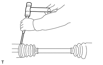
Using a flat tip screwdriver or needle-nose pliers, loosen the boot band on the large end of rear drive shaft inboard joint boot clamp.
- NOTICE:
-
Do not damage the rear drive shaft joint boot.
42347A
2.REMOVE REAR NO.2 DRIVE SHAFT INBOARD JOINT BOOT CLAMP
- HINT:
-
Perform the same procedure as for the rear drive shaft inboard joint boot clamp.
3.REMOVE REAR NO.2 DRIVE SHAFT OUTBOARD JOINT BOOT CLAMP
- HINT:
-
Perform the same procedure as for the rear drive shaft inboard joint boot clamp.
42346A
4.REMOVE REAR DRIVE SHAFT OUTBOARD JOINT BOOT CLAMP
- HINT:
-
Perform the same procedure as for the rear drive shaft inboard joint boot clamp.
5.REMOVE HOLE SNAP RING
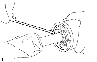
Using screwdriver, remove the round hole snap ring at the neck of the rear drive shaft inboard joint assembly LH.
6.REMOVE REAR DRIVE SHAFT INBOARD JOINT ASSEMBLY LH
Take out the rear drive shaft inboard joint assembly LH from the shaft assembly.
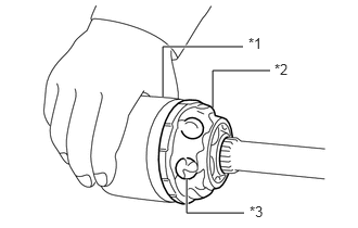
Wipe off the grease and take out the balls.
| *1 | Rear Drive Shaft Inboard Joint Assembly LH |
| *2 | Grease |
| *3 | Balls (8 Pieces) |
- NOTICE:
-
The grease is a special grease (grease for constant velocity joints). Do not mix it with other greases.
- HINT:
-
Disassemble exercising care not to lose the balls (8 pieces).
To remove the EDJ cage from the EDJ inner race, turn the EDJ cage by a half pitch to the track groove of the EDJ inner race and shift the EDJ cage.
7.REMOVE EDJ INNER RACE
Using pliers, remove the snap ring fixing the EDJ inner race to the shaft.
Remove the EDJ inner race.
8.REMOVE REAR DRIVE SHAFT JOINT BOOT (for RH Side)
Disconnect the EDJ cage from the shaft and remove the rear drive shaft joint boot.
- NOTICE:
-
Wrap the shaft splines with vinyl tape to protect the boot from scratches.
9.REMOVE REAR DRIVE SHAFT JOINT BOOT (for LH Side)
- HINT:
-
Use the same procedure as for the RH side.