RM2090E
_56
Audio / Visual / Telematics
_060692
AUDIO / VIDEO
_0297650
AUDIO AND VISUAL SYSTEM
J
AUDIO / VIDEO AUDIO AND VISUAL SYSTEM Radio Receiver Power Source Circuit
DESCRIPTION
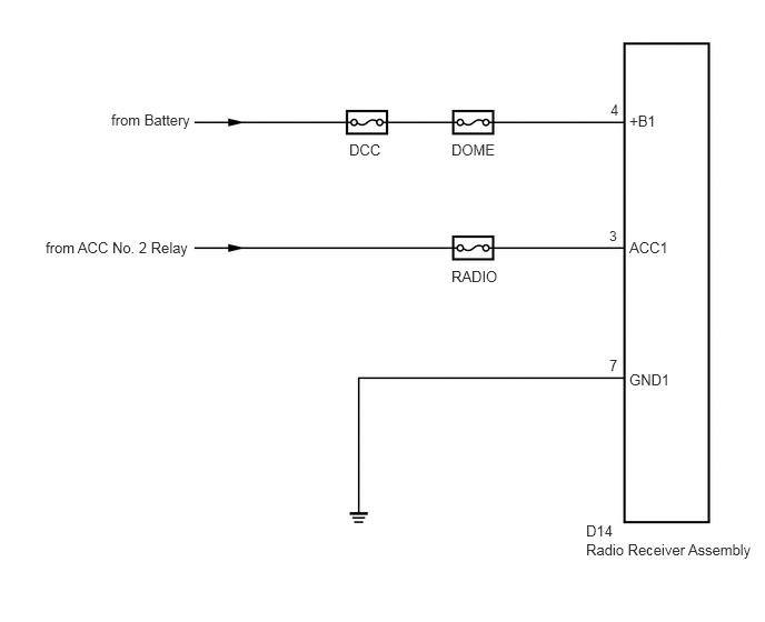
This circuit provides power to the radio receiver assembly.
WIRING DIAGRAM
5.708,2.135 5.865,2.313
0.156,0.177
9
false
3
1.042,1.042 1.813,1.365
0.771,0.323
10
false
from Battery
0.427,2.24 1.823,2.552
1.396,0.313
10
false
from ACC No. 2 Relay
3.271,1.323 3.729,1.656
0.458,0.333
10
false
DCC
4.229,1.323 4.688,1.656
0.458,0.333
10
false
DOME
4.229,2.51 4.74,2.844
0.51,0.333
10
false
RADIO
5.719,0.948 5.865,1.135
0.146,0.188
10
false
4
5.708,3.344 5.833,3.51
0.125,0.167
10
false
7
5.896,1.052 6.208,1.271
0.313,0.219
10
false
+B1
5.896,2.24 6.302,2.552
0.406,0.313
10
false
ACC1
5.896,3.479 6.438,3.844
0.542,0.365
10
false
GND1
5.49,4.896 5.802,5.063
0.313,0.167
10
false
D14
5.49,5.073 7.115,5.375
1.625,0.302
10
false
Radio Receiver Assembly
CAUTION / NOTICE / HINT
- NOTICE:
-
Inspect the fuses for circuits related to this system before performing the following inspection procedure.
PROCEDURE
1.CHECK HARNESS AND CONNECTOR (RADIO RECEIVER ASSEMBLY - BATTERY, BODY GROUND)
a.
Disconnect the radio receiver assembly connector.
b.
Measure the resistance according to the value(s) in the table below.
- Standard Resistance:
Tester Connection Condition Specified Condition D14-7 (GND1) - Body ground Always Below 1 Ω
c.
Measure the voltage according to the value(s) in the table below.
- Standard Voltage:
Tester Connection Condition Specified Condition D14-4 (+B1) - D14-7 (GND1) Always 11 to 14 V D14-3 (ACC1) - D14-7 (GND1) Ignition switch ACC 11 to 14 V
OK
PROCEED TO NEXT SUSPECTED AREA SHOWN IN PROBLEM SYMPTOMS TABLE
NG
REPAIR OR REPLACE HARNESS OR CONNECTOR