FA20 BATTERY / CHARGING GENERATOR DISASSEMBLY
PROCEDURE

 27039
1.REMOVE GENERATOR REAR END COVER
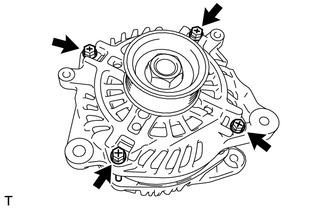
Remove the 4 through bolts.
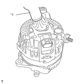
Using the heat gun, heat the generator rear end cover.
- Heating Temperature:
Item Temperature Generator Rear End Cover 50 to 60°C (122 to 140°F)
| *1 | Heat gun |
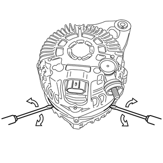
Insert the 2 screw drivers, and remove the generator rear end cover as shown in the illustration.
27411
2.REMOVE GENERATOR PULLEY
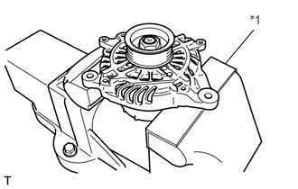
Mount the generator in a vise between aluminum plates.
| *1 | Aluminium plate |
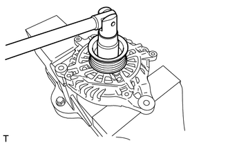
Remove the nut and generator pulley.
27310
3.REMOVE GENERATOR DRIVE END FRAME ASSEMBLY
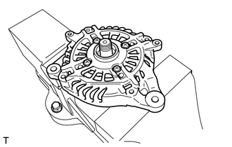
Remove the generator drive end frame assembly from the generator rotor assembly.
27310B
4.REMOVE GENERATOR DRIVE END FRAME BEARING
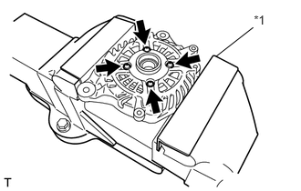
Mount the generator drive end frame assembly in a vise between aluminum plates.
Remove the 4 bolts and bearing retainer.
| *1 | Aluminium plate |
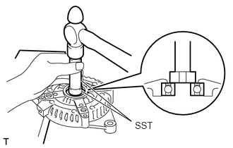
Using SST and a hammer, tap out the bearing.
- SST
- 09950-60010 (09951-00250)
09950-70010 (09951-07100)
27330A
5.REMOVE GENERATOR ROTOR BEARING
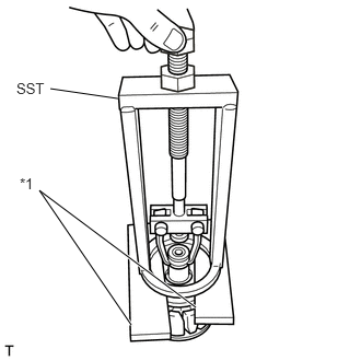
Set the SST to the generator rotor assembly between wooden blocks.
- SST
- 09387-00041
| *1 | Wooden block |
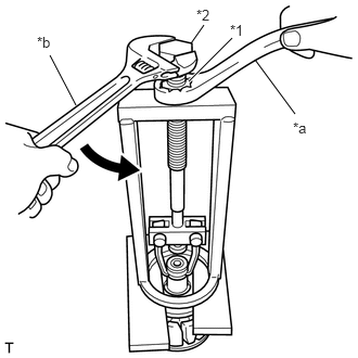
Hold the SST nut, and turn the SST bolt to remove the generator rotor bearing.
| *1 | SST Nut |
| *2 | SST Bolt |
| *a | Hold |
| *b | Turn |
27360
6.REMOVE GENERATOR COIL ASSEMBLY
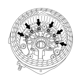
Remove the 6 bolts and generator coil assembly.
27370
7.REMOVE GENERATOR BRUSH HOLDER ASSEMBLY
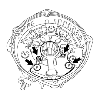
Remove the 4 bolts and generator brush holder assembly.
8.REMOVE BRUSH
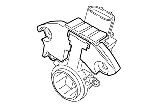
Remove the cover A from the brush holder assembly.
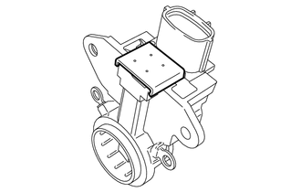
Remove the cover B from the brush holder assembly.
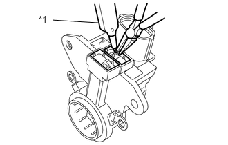
Using a soldering iron, separate the 2 brushes from the brush holder assembly.
| *1 | Soldering iron |
27357
9.REMOVE GENERATOR HOLDER WITH RECTIFIER
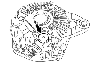
Remove the terminal cover.
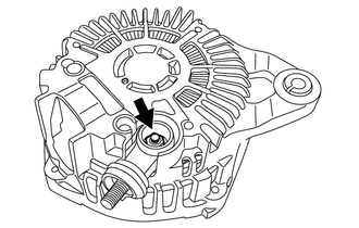
Remove the nut and the terminal.
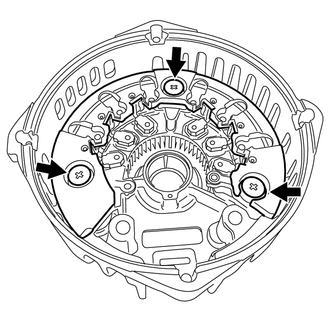
Remove the 3 bolts and the generator holder with rectifier.