FA20 BATTERY / CHARGING GENERATOR REASSEMBLY
PROCEDURE

 27357
1.INSTALL GENERATOR HOLDER WITH RECTIFIER
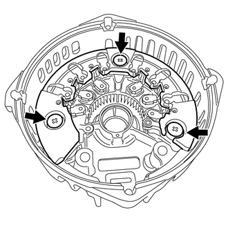
Install the generator holder with rectifier with the 3 bolts.
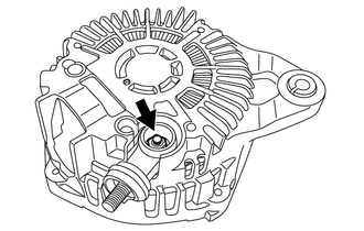
Install the terminal with the nut.
- Torque:
- 8.9 N*m (91 kgf*cm, 79 in.*lbf)
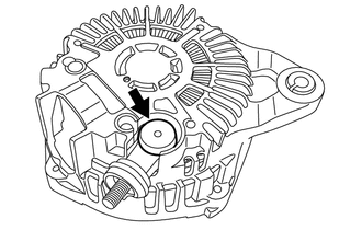
Install the terminal cover.
2.INSTALL BRUSH
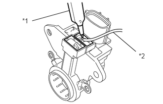
Using a soldering iron, install the 2 brushes to the brush holder assembly.
| *1 | Soldering iron |
| *2 | Solder |
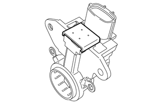
Install the cover B to the brush holder assembly.
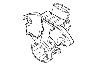
Install the cover A to the brush holder assembly.
27370
3.INSTALL GENERATOR BRUSH HOLDER ASSEMBLY
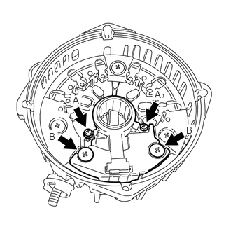
Install the generator brush holder assembly with the 4 bolts.
- Torque:
- Bolt A : 2.0 N*m (20 kgf*cm, 18 in.*lbf)
- Bolt B : 3.9 N*m (40 kgf*cm, 35 in.*lbf)
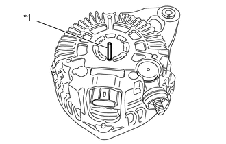
While pushing the 2 brushes into the generator rear end cover, insert a 1.0 mm (0.0394 in.) pin into the generator rear end cover.
- NOTICE:
-
Remove the pin after reassembling the generator.
| *1 | Pin 1.0 mm (0.0394 in.) |
27360
4.INSTALL GENERATOR COIL ASSEMBLY
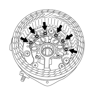
Install the generator coil assembly with the 6 bolts.
- Torque:
- 2.0 N*m (20 kgf*cm, 18 in.*lbf)
27330A
5.INSTALL GENERATOR ROTOR BEARING
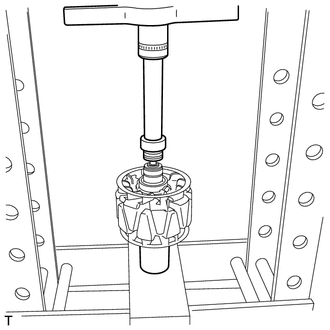
Using SST and a press, press in a new generator rotor bearing.
- SST
- 09632-36010
09820-36010
27310B
6.INSTALL GENERATOR DRIVE END FRAME BEARING
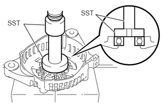
Using SST and a press, press in a new generator drive end frame bearing.
- SST
- 09950-60010 (09951-00520)
09950-70010 (09951-07100)
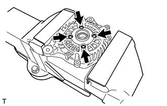
Install the bearing retainer with the 4 screws.
- Torque:
- 3.9 N*m (40 kgf*cm, 35 in.*lbf)
27310
7.INSTALL GENERATOR DRIVE END FRAME ASSEMBLY
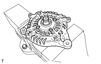
Install the generator drive end frame assembly to the generator rotor assembly.
27411
8.INSTALL GENERATOR PULLEY
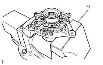
Mount the generator in a vise between aluminum plates.
| *1 | Aluminium plate |
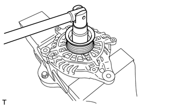
Install the generator pulley with the nut.
- Torque:
- 108 N*m (1101 kgf*cm, 80 ft.*lbf)
27039
9.INSTALL GENERATOR REAR END COVER
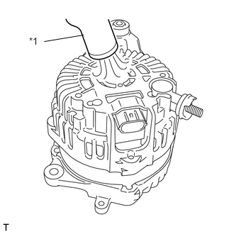
using the heat gun, heat the generator rear end cover.
- Heating Temperature:
Item Temperature Generator Rear End Cover 50 to 60°C (122 to 140°F)
| *1 | Heat gun |
Install the generator rear end cover.
Pull out the pin of the generator rear end cover.
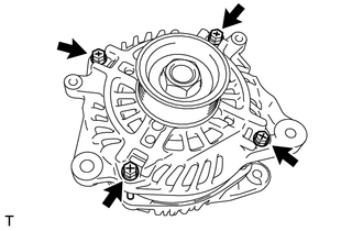
Install the 4 through bolts.
- Torque:
- 4.4 N*m (45 kgf*cm, 39 in.*lbf)