RM2090E
_57
Power Source / Network
_060693
FA20 BATTERY / CHARGING
_0297661
CHARGING SYSTEM
U
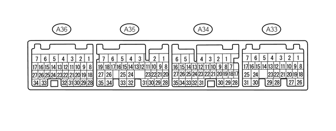
FA20 BATTERY / CHARGING CHARGING SYSTEM TERMINALS OF ECU
CHECK ECM
5.677,0.542 5.938,0.719
0.26,0.177
10
false
A33
4.219,0.542 4.479,0.719
0.26,0.177
10
false
A34
2.646,0.542 2.906,0.719
0.26,0.177
10
false
A35
1.198,0.542 1.458,0.719
0.26,0.177
10
false
A36
a.
Measure the resistance, voltage and waveform according to the value(s) in the table below.
| Terminal No.
(Symbol) |
Wiring Color | Terminal Description | Condition | Specified Condition |
|---|---|---|---|---|
| A33-2 (BATT) - A34-1 (E03) | W - B-R | Battery power | Always | 11 to 14 V |
| A33-11 (IB) - A35-30 (EPA2) | R-B - Y-B | Battery current sensor | Ignition switch ON | 0.5 to 4.5 V |
| A33-24 (THB) - A35-30 (EPA2) | R-W - Y-B | Battery temperature sensor | Ignition switch ON 20 to 50°C (68 to 122°F) | 1.1 to 2.4 V |
| A34-1 (E03) - Body ground | B-R - Body ground | Body ground | Always | Below 1 Ω |
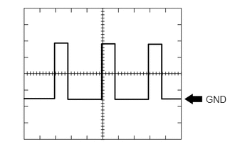
| A35-18 (ALT) - A34-1 (E03) | V - B-R | Generator | Idling with warm engine | Pulse generation (See waveform 1) |
| A35-22 (VCP2) - A35-30 (EPA2) | G-B - Y-B | Power source of battery current sensor assembly | Ignition switch ON | 4.5 to 5.5 V |
If the result is not as specified, the ECU may have a malfunction.
b.
3.01,1.375 3.333,1.542
0.323,0.167
10
false
GND
WAVEFORM 1
| Tester Connection | Tool Setting | Vehicle Condition | Specified Condition |
|---|---|---|---|
| A35-18 (ALT) - A34-1 (E03) | 2 V/DIV., 2 msec./DIV. | Idling with warm engine | Correct waveform as shown in illustration |
- HINT:
- ·
The oscilloscope waveform shown in the illustration is an example for reference only. Noise, chattering, etc. are not shown.
·A constant value is not output, as the duty ratio varies depending on the electrical load and battery condition.