RM2090E
_57
Power Source / Network
_060694
POWER DISTRIBUTION
_0297662
ELECTRIC POWER CONTROL SYSTEM
U
POWER DISTRIBUTION ELECTRIC POWER CONTROL SYSTEM TERMINALS OF ECU
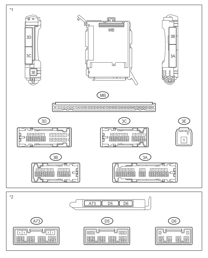
CHECK INSTRUMENT PANEL JUNCTION BLOCK ASSEMBLY AND MAIN BODY ECU (NETWORK GATEWAY ECU)
0.327,6.683 0.513,6.844
0.186,0.161
10
*2
0.327,0.249 0.513,0.410
0.186,0.161
10
*1
3.441,3.196 3.673,3.353
0.231,0.156
10
MB
3.737,0.945 3.975,1.102
0.238,0.156
10
MB
0.905,1.834 1.120,1.991
0.215,0.156
10
3C
0.905,1.199 1.120,1.355
0.215,0.156
10
3D
1.07,2.409 1.285,2.566
0.215,0.156
10
3E
5.869,1.842 6.084,1.998
0.215,0.156
10
3A
5.869,1.17 6.084,1.326
0.215,0.156
10
3B
6.255,4.086 6.486,4.243
0.231,0.156
10
3E
4.195,4.086 4.426,4.243
0.231,0.156
10
3C
1.428,4.086 1.659,4.243
0.231,0.156
10
3D
4.916,5.329 5.148,5.485
0.231,0.156
10
3A
1.83,5.329 2.061,5.485
0.231,0.156
10
3B
4.252,6.919 4.467,7.075
0.215,0.156
10
D6
3.059,6.919 3.339,7.075
0.280,0.156
10
A73
3.711,6.919 3.926,7.075
0.215,0.156
10
D5
5.908,7.526 6.140,7.682
0.231,0.156
10
D6
3.604,7.526 3.835,7.682
0.231,0.156
10
D5
1.14,7.526 1.424,7.682
0.284,0.156
10
A73
0.216,0.166 6.958,6.463
6.742,6.297
0.216,6.596 6.958,8.62
6.742,2.024
| *1 | Instrument Panel Junction Block Assembly | *2 | Main Body ECU (Network Gateway ECU) |
a.
Measure the voltage and resistance according to the value(s) in the table below.
- HINT:
-
With the connectors connected, inspect from the rear side of the connectors.
| Terminal No.
(Symbol) |
Wiring Color | Terminal Description | Condition | Specified Condition |
|---|---|---|---|---|
| 3A-15 - Body ground | W - Body ground | IG power supply | Ignition switch ON | 11 to 14V |
| 3A-20 - Body ground | SB - Body ground | ACC power supply | Ignition switch ACC | 11 to 14V |
| 3A-27 - Body ground | G-R - Body ground | Battery power supply | Always | 11 to 14V |
| 3C-19 - Body ground | L-R - Body ground | Battery power supply | Always | 11 to 14V |
| 3E-1 - Body ground | B-R - Body ground | Battery power supply | Always | 11 to 14V |
| 3A-12 - Body ground | B - Body ground | Ground | Always | Below 1 Ω |
| 3A-13 - Body ground | B - Body ground | Ground | Always | Below 1 Ω |
| 3B-18 - Body ground | B-Y - Body ground | Ground | Always | Below 1 Ω |
| D6-1 (GND) - Body ground | B - Body ground | Ground | Always | Below 1 Ω |
| A73-4 (GND) - Body ground | B-Y - Body ground | Ground | Always | Below 1 Ω |
b.
Remove the main body ECU (network gateway ECU) from the instrument panel junction block assembly.
c.
Measure the voltage and resistance according to the value(s) in the table below.
| Terminal No.
(Symbol) |
Wiring Color | Terminal Description | Condition | Specified Condition |
|---|---|---|---|---|
| MB-1 (BECU) - Body ground | None - Body ground | Battery power supply back up voltage | Always | 11 to 14V |
| MB-8 (IG) - Body ground | None - Body ground | IG power supply | Ignition switch ON | 11 to 14V |
| MB-9 (ACC) - Body ground | None - Body ground | ACC power supply | Ignition switch ACC | 11 to 14V |
| MB-32 (BMPX) - Body ground | None - Body ground | Battery power supply control voltage | Always | 11 to 14V |
| MB-11 (GND) - Body ground | None - Body ground | Ground | Always | Below 1 Ω |