RM2090E
_57
Power Source / Network
_060694
POWER DISTRIBUTION
_0297663
BATTERY CURRENT SENSOR
G
POWER DISTRIBUTION BATTERY CURRENT SENSOR INSPECTION
PROCEDURE

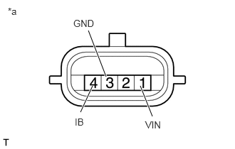
 1.INSPECT BATTERY CURRENT SENSOR ASSEMBLY
1.354,1.26 1.177,1.646
true
1.552,1.125 1.292,0.448
true
2.052,1.26 2.229,1.708
true
1.073,0.26 1.417,0.427
0.344,0.167
10
false
GND
2.125,1.75 2.396,1.917
0.271,0.167
10
false
VIN
1.094,1.708 1.281,1.885
0.188,0.177
10
false
IB
0.115,0.083 0.292,0.26
0.177,0.177
10
false
*a
a.
Check the resistance of the battery current sensor assembly.
i.
Measure the resistance according to the value(s) in the table below.
- Standard Resistance:
Tester Connection Condition Specified Condition 1 (VIN) - 3 (GND) Always 3 to 10 kΩ 1 (VIN) - 4 (IB) Always Below 0.5 kΩ 3 (GND) - 4 (IB) Always 3 to 10 kΩ
If the result is not as specified, replace the battery current sensor assembly.
| *a | Component without harness connected
(Battery Current Sensor Assembly) |
b.
1.448,1.521 1.594,1.094
true
2.125,1.521 1.99,1.094
true
0.125,0.083 0.313,0.271
0.188,0.188
10
false
*a
0.135,1.698 0.333,1.896
0.198,0.198
10
false
*b
1.698,4.344 1.875,4.521
0.177,0.177
10
false
*c
1.25,1.563 1.615,1.75
0.365,0.188
10
false
GND
2.021,1.563 2.323,1.729
0.302,0.167
10
false
THB
1.177,3.677 1.302,3.833
0.125,0.156
10
false
0
1.469,3.885 1.688,4.052
0.219,0.167
10
false
20
0.188,3.25 0.365,3.427
0.177,0.177
10
false
10
0.177,2.938 0.365,3.115
0.188,0.177
10
false
20
0.177,2.656 0.375,2.833
0.198,0.177
10
false
30
0.177,2.365 0.365,2.552
0.188,0.188
10
false
40
0.177,2.073 0.375,2.25
0.198,0.177
10
false
50
0.271,3.563 0.375,3.719
0.104,0.156
10
false
0
1.844,3.677 2.042,3.833
0.198,0.156
10
false
40
2.219,3.896 2.427,4.073
0.208,0.177
10
false
60
2.573,3.677 2.75,3.844
0.177,0.167
10
false
80
2.927,3.896 3.198,4.063
0.271,0.167
10
false
100
0.719,3.885 0.958,4.052
0.24,0.167
10
false
-20
0.396,3.677 0.635,3.844
0.24,0.167
10
false
-40
1.198,3.885 1.458,4.063
0.26,0.177
10
false
(32)
0.406,3.885 0.708,4.052
0.302,0.167
10
false
(-40)
0.719,4.052 0.958,4.219
0.24,0.167
10
false
(-4)
1.438,4.052 1.688,4.219
0.25,0.167
10
false
(68)
1.885,3.896 2.219,4.094
0.333,0.198
10
false
(104)
2.146,4.052 2.469,4.229
0.323,0.177
10
false
(140)
2.594,3.896 2.927,4.063
0.333,0.167
10
false
(176)
2.896,4.073 3.24,4.271
0.344,0.198
10
false
(212)
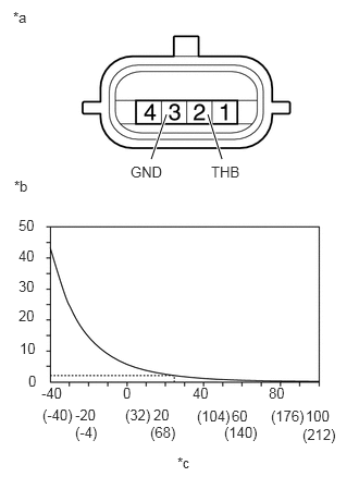
Check the resistance of the battery current sensor assembly.
i.
Measure the resistance according to the value(s) in the table below.
- Standard Resistance:
Tester Connection Condition Specified Condition 2 (THB) - 3 (GND) 20°C (68°F) to 30°C (86°F) 1.5 to 2.6 kΩ
If the result is not as specified, replace the battery current sensor assembly.
| *a | Component without harness connected
(Battery Current Sensor Assembly) |
| *b | [kΩ] |
| *c | [°C (°F)] |
- HINT:
-
The "Condition" indicates the temperature in the vicinity of the sensor, not of the actual sensor itself.