RM2090E
_58
Vehicle Interior
_060704
HEATING / AIR CONDITIONING
_0297735
AIR CONDITIONING SYSTEM(for Manual Air Conditioning System)
U
HEATING / AIR CONDITIONING AIR CONDITIONING SYSTEM(for Manual Air Conditioning System) TERMINALS OF ECU
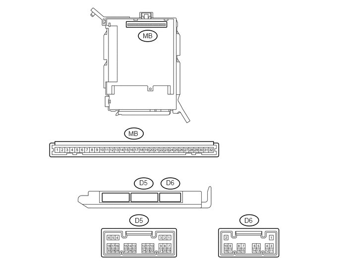
INSTRUMENT PANEL JUNCTION BLOCK ASSEMBLY, MAIN BODY ECU (NETWORK GATEWAY ECU)
3,0.667 3.229,0.823
0.229,0.156
10
false
MB
2.698,2.719 2.927,2.875
0.229,0.156
10
false
MB
2.927,3.75 3.135,3.906
0.208,0.156
10
false
D5
3.49,3.75 3.698,3.906
0.208,0.156
10
false
D6
2.833,4.542 3.042,4.698
0.208,0.156
10
false
D5
5.135,4.542 5.344,4.698
0.208,0.156
10
false
D6
a.
Remove the main body ECU (network gateway ECU) from the instrument panel junction block assembly.
b.
Measure the values on the wire harness side with the connector disconnected.
| Terminal No.
(Symbol) |
Wiring Color | Description | Condition | Specified Condition |
|---|---|---|---|---|
| MB8(G) - Body ground | - | Power source (IG) | Ignition switch : ON | 11 to 14 V |
| MB9(ACC) - Body ground | - | Power source (ACC) | Ignition switch : ACC | 11 to 14 V |
| MB11(GND) - Body ground | - | Ground for main power supply | Always | Below 1 Ω |
If the result is not as specified, there may be a malfunction in the wire harness.
c.
Install the main body ECU (network gateway ECU) to the instrument panel junction block assembly.
d.
Measure the voltage and resistance according to the value(s) in the table below.
- HINT:
-
Measure the values on the wire harness side with the connector disconnected.
| Terminal No.
(Symbol) |
Wiring Color | Description | Condition | Specified Condition |
|---|---|---|---|---|
| D5- 13(CANL) - D5-14(CANH) | LG - P | CAN communication system | CAN communication circuit | Pulse generation |
| Terminal No.
(Symbol) |
Wiring Color | Description | Condition | Specified Condition |
|---|---|---|---|---|
| D6-17 - Body ground | Y - Body ground | A/C switch signal | ·
Ignition switch : ON ·
A/C switch : ON |
Below 1 Ω |
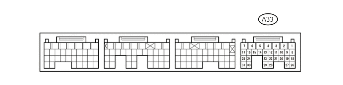
ECM
5.469,0.323 5.74,0.469
0.271,0.146
10
false
A33
- HINT:
-
Check from the rear of the connector while it is connected to the Air conditioning control assembly.
| Terminal No.
(Symbol) |
Wiring Color | Terminal Description | Condition | Specified Condition |
|---|---|---|---|---|
| A33-8(ACP) - Body ground | G - Body ground | Air conditioning pressure switch signal | Engine running
A/C system operating Refrigerant pressure: Abnormal |
Below 1 V |
| Engine running
A/C system operating Refrigerant pressure: Normal |
11 to 14 V | |||
| A33- 18(CANL) - A33-19(CANH) | B-P - O | CAN communication system | CAN communication circuit | Pulse generation |