RM2090E
_58
Vehicle Interior
_060704
HEATING / AIR CONDITIONING
_0297751
AIR CONDITIONING PANEL(for Manual Air Conditioning System)
G
HEATING / AIR CONDITIONING AIR CONDITIONING PANEL(for Manual Air Conditioning System) INSPECTION
PROCEDURE

 55903A
1.INSPECT NO. 3 HEATER CONTROL SUB-ASSEMBLY
a.
2.702,0.14 2.886,0.319
0.184,0.179
10
*1
0.404,1.956 0.671,2.135
0.267,0.179
10
*a
2.744,0.315 1.897,1.01
false
1.803,3.148 2.082,3.320
0.279,0.172
10
A/C
2.199,3.148 2.327,3.307
0.128,0.159
10
B
1.273,3.148 1.635,3.305
0.362,0.157
10
AND
2.086,2.89 2.238,3.133
false
1.947,2.89 1.947,3.13
false
1.819,2.891 1.488,3.141
false
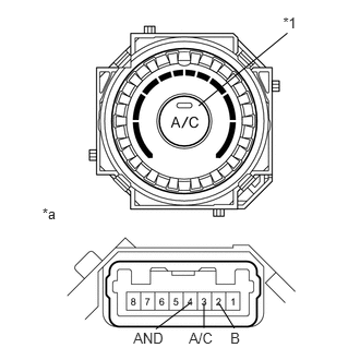
Check the heater control assembly resistance.
b.
Measure the resistance according to the value(s) in the table below.
- Standard Resistance:
Tester Connection Switch Condition Specified Condition 2(B) - 3(A/C) A/C switch OFF 10 kΩ or higher 2(B) - 4(AND) A/C switch OFF 10 kΩ or higher 3(A/C) - 4(AND) Always Below 1 Ω 2(B) - 3(A/C) A/C switch ON Below 1 Ω 2(B) - 4(AND) A/C switch ON Below 1 Ω 5 - 6 Always Below 1 Ω
| *1 | A/C Switch |
| *a | Component without harness connected
(No. 3 heater control sub-assembly) |
c.
Check that the A/C Switch illumination.
- OK:
Measurement Condition Specified Condition Battery positive (+) → 5
Battery negative (-) → 6illuminates
d.
Check that the indicator light.
- Standard:
Tester Connection Switch Condition Specified Condition Battery positive (+) → 2
Battery negative (-) → 4A/C switch OFF go out Battery positive (+) → 2
Battery negative (-) → 4A/C switch ON come on
55902B
2.INSPECT HEATER CONTROL SUB-ASSEMBLY
a.
0.458,2.188 0.625,2.354
0.167,0.167
10
false
*f
2.688,0.604 2.854,0.771
0.167,0.167
10
false
*e
2.24,0.167 2.406,0.333
0.167,0.167
10
false
*d
1.615,0.01 1.781,0.177
0.167,0.167
10
false
*c
0.938,0.156 1.104,0.323
0.167,0.167
10
false
*b
0.458,0.604 0.625,0.771
0.167,0.167
10
false
*a
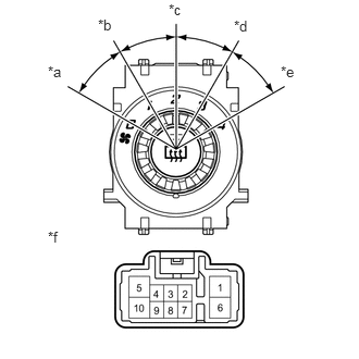
Check the heater control assembly resistance.
b.
Measure the resistance according to the value(s) in the table below.
- Standard Resistance:
Tester Connection Switch Condition Specified Condition each terminal - 5 A/C switch OFF 10 kΩ or higher 10 - 5 A/C switch LO Below 1 Ω 10 - 5 - 3 A/C switch LO - M1 Below 1 Ω 10 - 5 - 3 A/C switch M1 Below 1 Ω 10 - 5 - 3 - 6 A/C switch M1 - M2 Below 1 Ω 10 - 5 - 6 A/C switch M2 Below 1 Ω 10 - 5 - 6 - 1 A/C switch M2 - HI Below 1 Ω 10 - 5 - 1 A/C switch HI Below 1 Ω
c.
| *a | OFF |
| *b | LO |
| *c | M1 |
| *d | M2 |
| *e | HI |
| *f | Component without harness connected
(heater control sub-assembly) |
d.
2.563,0.403 2.731,0.565
0.168,0.162
10
*1
0.488,2.067 0.667,2.260
0.179,0.193
10
*a
1.805,1.132 2.559,0.554
false
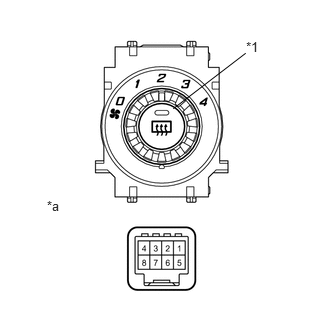
Check the heater control assembly resistance.
e.
Measure the resistance according to the value(s) in the table below.
- Standard Resistance:
Tester Connection Switch Condition Specified Condition 2 - 4 Rr DEF switch OFF 10 kΩ or higher 2 - 4 Rr DEF switch ON Below 1 Ω
| *1 | Rr DEF switch |
| *a | Component without harness connected
(heater control sub-assembly) |
f.
Check that the Rr DEF switch illumination.
- OK:
Measurement Condition Specified Condition Battery positive (+) → 7
Battery negative (-) → 5illuminates
g.
Check that the indicator light.
- Standard:
Tester Connection Switch Condition Specified Condition Battery positive (+) → 6
Battery negative (-) → 8Rr DEF switch OFF go out Battery positive (+) → 6
Battery negative (-) → 8Rr DEF switch ON come on
55901D
3.INSPECT NO. 1 HEATER CONTROL SUB-ASSEMBLY
a.
2.584,0.145 2.753,0.318
0.169,0.174
10
*1
1.877,0.978 2.577,0.304
false
0.449,2.018 0.618,2.192
0.169,0.174
10
*a
1.283,3.115 1.643,3.294
0.360,0.179
10
LED+
1.68,2.862 1.481,3.102
false
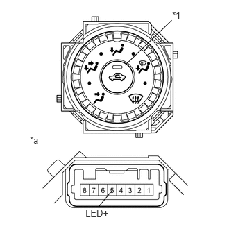
Check that the FRS switch illumination.
- OK:
Measurement Condition Specified Condition Battery positive (+) → 7
Battery negative (-) → 6illuminates
| *1 | FRS switch |
| *a | Component without harness connected
(No. 1 heater control sub-assembly) |
b.
Check that the indicator light.
- Standard:
Tester Connection Switch Condition Specified Condition Battery positive (+) → 5(LED+)
Battery negative (-) → 4FRS switch OFF go out Battery positive (+) → 5(LED+)
Battery negative (-) → 4FRS switch ON come on