INTERIOR PANELS / TRIM FRONT CONSOLE BOX REMOVAL
PROCEDURE

 58818A
1.REMOVE FRONT CONSOLE BOX COVER (w/ Entry and Start System)
Move the shift lever to N.
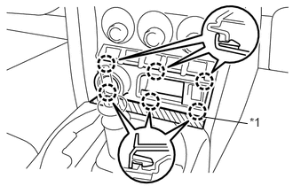
Apply protective tape to the area shown in the illustration.
| *1 | Protective Tape |
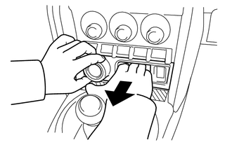
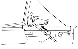
Disengage the 6 claws and remove the front console box cover.
- HINT:
-
Hold the engine switch area and the inside of the pocket with your hand, and pull off the front console box cover.
- HINT:
-
Remove the instrument panel finish panel end RH, and then push the reverse side of the front console box cover with a bar (tool handle, etc.) to remove it.
| *1 | Bar |
- NOTICE:
-
Do not push the switches or the antenna with the bar (tool handle, etc.).
Disconnect each connector.
89611
2.REMOVE PUSH START SWITCH (w/ Entry and Start System)
89992
3.REMOVE INDOOR ELECTRICAL KEY OSCILLATOR (w/ Entry and Start System)
58818A
4.REMOVE FRONT CONSOLE BOX COVER (w/o Entry and Start System)
Move the shift lever to N.
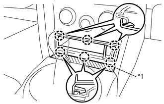
Apply protective tape to the area shown in the illustration.
| *1 | Protective Tape |
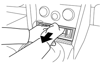
Disengage the 6 claws and remove the front console box cover.
- HINT:
-
Hold the inside of the pocket with your hand, and pull off the front console box cover.
- HINT:
-
 1.711,1.726 1.890,1.908 0.179,0.182 10 *1 1.905,1.791 2.184,1.63 false
-
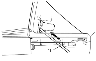
Remove the instrument panel finish panel end RH, and then push the reverse side of the front console box cover with a bar (tool handle, etc.) to remove it.
Text in Illustration *1 Bar
- NOTICE:
-
Do not push the switches or the antenna with the bar (tool handle, etc.).
86190C
5.REMOVE NO. 1 STEREO JACK ADAPTER ASSEMBLY (w/ Stereo Jack Adapter)
33504F
6.REMOVE SHIFT LEVER KNOB SUB-ASSEMBLY (for Automatic Transmission)
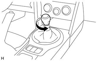
Turn the knob counterclockwise and remove the shift lever knob sub-assembly.
58804A
7.REMOVE UPPER CONSOLE PANEL SUB-ASSEMBLY (for Automatic Transmission)
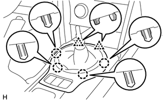
Disengage the 2 clips and 4 claws.
Disconnect each connector and remove the upper console panel sub-assembly.
35978
8.REMOVE SHIFT POSITION INDICATOR (for Automatic Transmission)
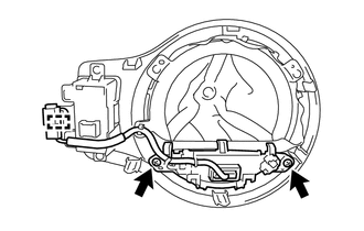
Remove the 2 screws.
Disengage the clamp to remove the shift position indicator.
58808
9.REMOVE SHIFTING HOLE COVER SUB-ASSEMBLY (for Automatic Transmission)
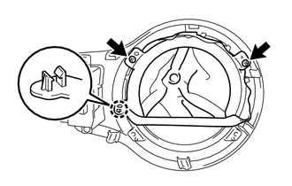
Remove the 2 screws.
Disengage the claw to remove the shifting hole cover sub-assembly.
84720J
10.REMOVE PATTERN SELECT SWITCH ASSEMBLY (for Automatic Transmission)
33504F
11.REMOVE SHIFT LEVER KNOB SUB-ASSEMBLY (for Manual Transmission)
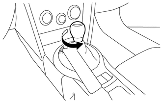
Turn the knob counterclockwise and remove the shift lever knob sub-assembly.
58804A
12.REMOVE UPPER CONSOLE PANEL SUB-ASSEMBLY (for Manual Transmission)
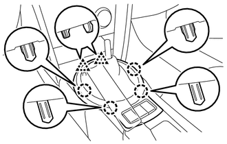
Disengage the 2 clips and 4 claws.
Disconnect each connector and remove the upper console panel sub-assembly.
58808
13.REMOVE SHIFTING HOLE COVER SUB-ASSEMBLY (for Manual Transmission)
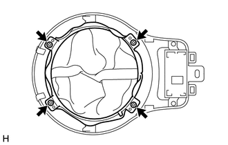
Remove the 4 screws and the shifting hole cover sub-assembly.
84720J
14.REMOVE PATTERN SELECT SWITCH ASSEMBLY (for Manual Transmission)
74103
15.REMOVE NO. 1 ASH RECEPTACLE SUB-ASSEMBLY (w/ Ashtray)
Remove the No. 1 ash receptacle sub-assembly.
55620B
16.REMOVE INSTRUMENT PANEL CUP HOLDER
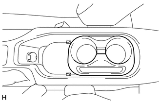
Remove the instrument panel cup holder.
55620A
17.REMOVE CUP HOLDER CUSHION
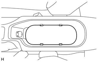
Remove the cup holder cushion.
58941A
18.REMOVE PARKING BRAKE HOLE COVER
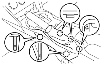
Disengage the 5 claws to remove the parking brake hole cover.
- NOTICE:
-
Remove the parking brake hole cover by pulling straight it up to disengage the claws, If not claws may be broken.
55436A
19.REMOVE INSTRUMENT PANEL FINISH PANEL END LH
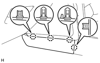
Disengage the 4 claws to remove the instrument panel finish panel end LH.
55435A
20.REMOVE INSTRUMENT PANEL FINISH PANEL END RH
- HINT:
-
Use the same procedure described for the LH side.
58810J
21.REMOVE CONSOLE BOX ASSEMBLY
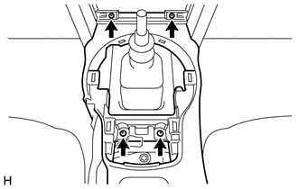
Remove the 4 screws.
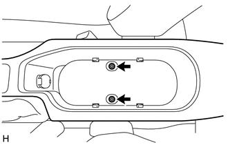
Remove the 2 bolts.
Disconnect each connector and remove the console box assembly.