LIGHTING (EXT) STOP LIGHT SWITCH INSTALLATION
CAUTION / NOTICE / HINT
- HINT:
- ·
Use the same procedure for RHD and LHD vehicles.
·The procedure listed below is for LHD vehicles.
PROCEDURE

 84340
1.INSTALL STOP LIGHT SWITCH ASSEMBLY
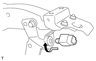
Insert the stop light switch assembly until the threaded sleeve hits the pedal.
- NOTICE:
-
When inserting the stop light switch assembly, support the pedal from behind so that the pedal is not pushed in.
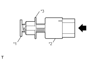
Insert the stop light switch assembly into the mounting adjuster until it slightly contacts the brake pedal.
| *1 | Brake Pedal |
| *2 | Stop Light Switch Assembly |
| *3 | Mounting Adjuster |
- NOTICE:
- ·
Do not push the brake pedal when inserting the stop light switch assembly.
·Support the brake pedal with one hand so that it does not move during the procedure.
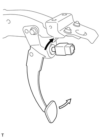
While pulling the brake pedal as far upwards as possible, rotate the stop light switch assembly one quarter-turn clockwise.
- NOTICE:
- ·
The stop light switch assembly must be installed last when assembling the brake pedal.
·Do not push too strongly when the stop light switch assembly touches the brake pedal.
·Do not push the brake pedal when inserting the stop light switch assembly.
·Support the brake pedal with one hand so that it does not move during the procedure.
·Apply less than 3.0 N*m (31 kgf*cm, 27 in.*lbf) rotational torque while rotating it clockwise (if itis difficult to rotate, reduce the force that you are pushing in the stop light switch assembly, and then rotate it.).
Connect the connector.
Adjust the stop light switch assembly.