BRAKE (FRONT) FRONT BRAKE(for Opposed Type Caliper) INSTALLATION
CAUTION / NOTICE / HINT
- HINT:
- ·
Use the same procedure for RH and LH sides.
·The procedure listed below is for LH side.
PROCEDURE

 43512
1.INSTALL FRONT DISC
When reusing the disc
Align the matchmarks placed when removing, and install the front disc to the axle hub.
When replacing the front disc
Install a new front disc to the axle hub and measure the disc runout (See page Brake>BRAKE (FRONT)>FRONT BRAKE(for Opposed Type Caliper)>INSPECTION).
Temporarily tighten the hub nuts and fix the front disc to the axle hub.
2.INSTALL FRONT DISC BRAKE CYLINDER SUB-ASSEMBLY
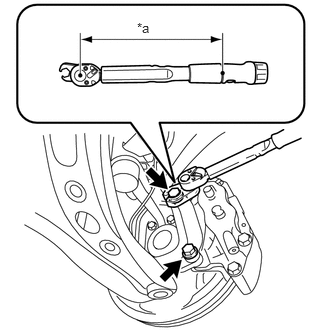
| *a | Torque Wrench Fulcrum Length |
Install the front disc brake cylinder assembly and front disc brake cylinder mounting with the 2 bolts.
- NOTICE:
-
When installing the front disc brake cylinder assembly and front disc brake cylinder mounting, hand-tighten the 2 bolts temporarily until they cannot be turned further, and tighten them to the specified torque.
- Torque:
- 120 N*m (1224 kgf*cm, 89 ft.*lbf)
- HINT:
- ·
When tightening the upper bolt, use a union nut wrench 17 mm.
·Calculate the torque wrench reading when changing the fulcrum length of the torque wrench.
Click hereGeneral>INTRODUCTION>REPAIR INSTRUCTION>PRECAUTION
·When using a union nut wrench (fulcrum length of 30 mm (1.18 in.)) + torque wrench (fulcrum length of 400 mm (15.7 in.)): 111.6 N*m (1138 kgf*cm, 82 ft.*lbf)
3.INSTALL FRONT DISC BRAKE CYLINDER SUB-ASSEMBLY
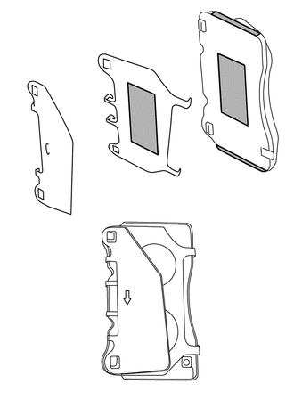

|
Disc Brake Grease |
Apply disc brake grease to the front disc brake pad and No. 1 anti-squeal sim.
Install the No. 2 anti-squeal sim to each front disc brake pad.
- HINT:
-
Install the No. 2 anti-squeal sim so that the arrow on the No. 2 anti-squeal sim faces down.
Install the No. 1 front disc brake pad support plate, 2 front disc brake cylinder slide pins and 2 pin hold clips to the front disk brake cylinder assembly.
47313A
4.CONNECT FRONT NO. 1 FLEXIBLE HOSE
Install the No. 1 front flexible hose to the disc brake cylinder assembly with 2 new gaskets and a new union bolt.
- Torque:
- 26 N*m (265 kgf*cm, 19 ft.*lbf)
5.ADD BRAKE FLUID
6.BLEED BRAKE LINE
7.INSPECT FOR BRAKE FLUID LEAK
8.INSPECT FLUID LEVEL
9.INSTALL FRONT WHEEL
- Torque:
- 120 N*m (1224 kgf*cm, 89 ft.*lbf)