Home › Audio / Visual / Telematics › PARK ASSIST / MONITORING › REAR VIEW MONITOR SYSTEM › from 2019.03
RM2090E _56 Audio / Visual / Telematics _082076 PARK ASSIST / MONITORING _0396236 REAR VIEW MONITOR SYSTEM J

PARK ASSIST / MONITORING  REAR VIEW MONITOR SYSTEM  Reverse Signal Circuit  


DESCRIPTION

The inner rear view mirror assembly receives a reverse signal from the back-up light switch assembly*1 or park/neutral position switch assembly*2.

*1: for Manual Transmission

*2: for Automatic Transmission


WIRING DIAGRAM
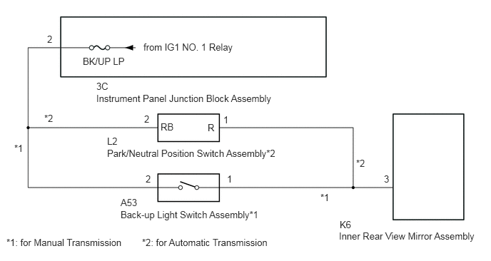
E389363E03
4.948,3.365 7.156,3.76 2.208,0.396 10 false Inner Rear View Mirror Assembly 1.76,3.052 4.156,3.417 2.396,0.365 10 false Back-up Light Switch Assembly*1 1.563,2.156 4.667,2.521 3.104,0.365 10 false Park/Neutral Position Switch Assembly*2 1.406,1.354 4.625,1.75 3.219,0.396 10 false Instrument Panel Junction Block Assembly 5.604,2.531 5.917,2.813 0.313,0.281 10 false 3 3.26,1.667 3.573,1.948 0.313,0.281 10 false 1 3.313,2.531 3.625,2.813 0.313,0.281 10 false 1 2.125,2.531 2.438,2.979 0.313,0.448 10 false 2 2.104,1.656 2.417,1.938 0.313,0.281 10 false 2 0.688,0.49 1,0.771 0.313,0.281 10 false 2 1.406,1.177 1.719,1.458 0.313,0.281 10 false 3C 3.031,1.781 3.344,2.063 0.313,0.281 10 false R 2.344,1.771 2.656,2.052 0.313,0.281 10 false RB 1.208,0.813 2.021,1.146 0.813,0.333 10 false BK/UP LP 2.094,0.604 3.667,0.938 1.573,0.333 10 false from IG1 NO. 1 Relay 1.76,2.875 2.188,3.198 0.427,0.323 10 false A53 1.563,1.979 1.99,2.302 0.427,0.323 10 false L2 4.958,3.198 5.385,3.521 0.427,0.323 10 false K6 0.094,3.458 2,3.802 1.906,0.344 10 false *1: for Manual Transmission 2.073,3.458 4.177,3.802 2.104,0.344 10 false *2: for Automatic Transmission 0.208,2.083 0.521,2.365 0.313,0.281 10 false *1 0.646,1.646 0.958,1.927 0.313,0.281 10 false *2 5.198,2.302 5.51,2.583 0.313,0.281 10 false *2 4.677,2.802 4.99,3.083 0.313,0.281 10 false *1

CAUTION / NOTICE / HINT

NOTICE:

Inspect the fuses for circuits related to this system before performing the following inspection procedure.


PROCEDURE

1.CHECK BACK-UP LIGHT
a.

Check that the back-up light comes on.

OK:

The back-up light comes on.


Result:
Proceed to
OK
NG


OK

2.CHECK HARNESS AND CONNECTOR (INNER REAR VIEW MIRROR ASSEMBLY - BACK-UP LIGHT SWITCH ASSEMBLY OR PARK/NEUTRAL POSITION SWITCH ASSEMBLY)

NG

2.CHECK HARNESS AND CONNECTOR (INNER REAR VIEW MIRROR ASSEMBLY - BACK-UP LIGHT SWITCH ASSEMBLY OR PARK/NEUTRAL POSITION SWITCH ASSEMBLY)
a.

Disconnect the K6 inner rear view mirror assembly connector.


b.

Disconnect the A53 back-up light switch assembly connector (for Manual Transmission).


c.

Disconnect the L2 park/neutral position switch assembly connector (for Automatic Transmission).


d.

Measure the resistance according to the value(s) in the table below.

Standard Resistance (for Manual Transmission):
Tester Connection Condition Specified Condition
A53-1 - K6-3 Always Below 1 Ω
A53-1 or K6-3 - Body ground Always 10 kΩ or higher


Standard Resistance (for Automatic Transmission):
Tester Connection Condition Specified Condition
L2-1 (R) - K6-3 Always Below 1 Ω
L2-1 (R) or K6-3 - Body ground Always 10 kΩ or higher


Result:
Proceed to
OK
NG


OK

PROCEED TO NEXT SUSPECTED AREA SHOWN IN PROBLEM SYMPTOMS TABLE

NG

REPAIR OR REPLACE HARNESS OR CONNECTOR