MIRROR (INT) INNER REAR VIEW MIRROR INSTALLATION
PROCEDURE

 1.INSTALL INNER REAR VIEW MIRROR SPRING PIN (w/o Rear View Monitor System)
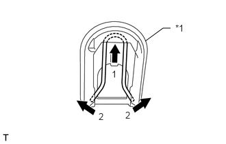
| *1 | Mirror base |
Install the new inner rear view mirror spring pin to the mirror base in the order shown in the illustration.
87810
2.INSTALL INNER REAR VIEW MIRROR ASSEMBLY (w/o Rear View Monitor System)
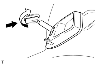
Slide and install the inner rear view mirror as shown in the illustration.
Turn the inner rear view mirror assembly in the direction indicated by the arrow in the illustration.
- HINT:
-
Turning direction can be either right or left.
3.INSTALL INNER REAR VIEW MIRROR ASSEMBLY (w/ Rear View Monitor System)
Engage the 3 claws to install the inner rear view mirror assembly as shown in the illustration.
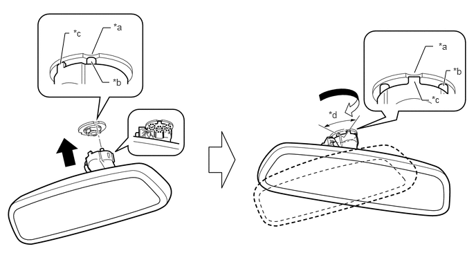
| *a | Notch | *b | Round Protrusion |
| *c | Square Protrusion | *d | Approximately 60° |
Connect the connector.
4.INSTALL LOWER MOUNT COVER (w/ Rear View Monitor System)
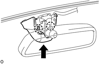
Engage the 2 claws to install the lower mount cover as shown in the illustration.
5.INSTALL MOUNT COVER ASSEMBLY (w/ Rear View Monitor System)
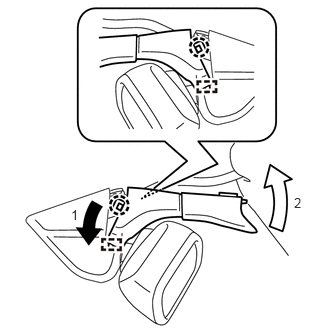
Engage the 2 guides and 2 claws to install the mount cover assembly as shown in the illustration.
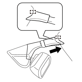
Slide the upper mount cover and engage the 2 guides as shown in the illustration.
- HINT:
-
Be sure to slide the upper mount cover until its rear end overlaps the roof headlining.