Home › Power Source / Network › POWER DISTRIBUTION › BATTERY CURRENT SENSOR › from 2019.03
RM2090E _57 Power Source / Network _060694 POWER DISTRIBUTION _0297663 BATTERY CURRENT SENSOR G

POWER DISTRIBUTION  BATTERY CURRENT SENSOR  INSPECTION  


PROCEDURE

Hide 1.INSPECT BATTERY CURRENT SENSOR ASSEMBLY (w/ 130 A Generator)
A266305C04
1.292,1.281 1.083,1.667 1.083,1.667 0.917,1.667 true 1.99,1.906 1.833,1.906 1.833,1.906 1.667,1.281 true 2.146,1.281 2.406,1.719 2.406,1.719 2.552,1.719 true 2.063,1.833 2.625,2.156 0.563,0.323 10 false GND 2.656,1.646 3.208,2.01 0.552,0.365 10 false VIN 0.719,1.594 1.094,1.865 0.375,0.271 10 false IB 0.115,0.083 0.49,0.469 0.375,0.385 10 false *a
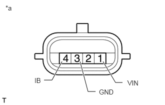
*a Component without harness connected
(Battery Current Sensor Assembly)


a.

Check the resistance of the battery current sensor assembly.

i.

Measure the resistance according to the value(s) in the table below.

Standard Resistance:
Tester Connection Condition Specified Condition
1 (VIN) - 3 (GND) Always 3 to 10 kΩ
1 (VIN) - 4 (IB) Always Below 0.5 kΩ
3 (GND) - 4 (IB) Always 3 to 10 kΩ


If the result is not as specified, replace the battery current sensor assembly.


b.
E247247C02
1.271,1.656 1.427,1.656 1.427,1.656 1.604,1.156 true 2.24,1.625 2.115,1.625 2.115,1.625 1.958,1.156 true 0.125,0.083 0.573,0.51 0.448,0.427 10 false *a 0.135,1.698 0.552,2.042 0.417,0.344 10 false *b 1.698,4.344 2.063,4.667 0.365,0.323 10 false *c 0.906,1.583 1.469,1.938 0.563,0.354 10 false GND 2.333,1.552 2.75,1.896 0.417,0.344 10 false THB 1.177,3.677 1.479,3.896 0.302,0.219 10 false 0 1.469,3.885 1.948,4.229 0.479,0.344 10 false 20 0.188,3.25 0.583,3.51 0.396,0.26 10 false 10 0.177,2.938 0.531,3.24 0.354,0.302 10 false 20 0.177,2.656 0.49,2.906 0.313,0.25 10 false 30 0.177,2.365 0.469,2.625 0.292,0.26 10 false 40 0.177,2.073 0.594,2.365 0.417,0.292 10 false 50 0.271,3.563 0.615,3.781 0.344,0.219 10 false 0 1.844,3.677 2.198,3.938 0.354,0.26 10 false 40 2.219,3.896 2.594,4.271 0.375,0.375 10 false 60 2.573,3.677 2.885,3.917 0.313,0.24 10 false 80 2.927,3.896 3.385,4.219 0.458,0.323 10 false 100 0.719,3.885 1.198,4.24 0.479,0.354 10 false -20 0.396,3.677 0.854,3.927 0.458,0.25 10 false -40 1.198,3.885 1.552,4.219 0.354,0.333 10 false (32) 0.406,3.885 0.802,4.156 0.396,0.271 10 false (-40) 0.719,4.052 1.083,4.385 0.365,0.333 10 false (-4) 1.438,4.052 1.844,4.406 0.406,0.354 10 false (68) 1.885,3.896 2.354,4.292 0.469,0.396 10 false (104) 2.146,4.052 2.635,4.396 0.49,0.344 10 false (140) 2.594,3.896 3.073,4.208 0.479,0.313 10 false (176) 2.896,4.073 3.354,4.448 0.458,0.375 10 false (212)
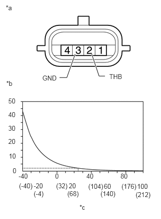
*a Component without harness connected
(Battery Current Sensor Assembly)
*b [kΩ]
*c [°C (°F)]


Check the resistance of the battery current sensor assembly.

i.

Measure the resistance according to the value(s) in the table below.

Standard Resistance:
Tester Connection Condition Specified Condition
2 (THB) - 3 (GND) 20°C (68°F) to 30°C (86°F) 1.5 to 2.6 kΩ


If the result is not as specified, replace the battery current sensor assembly.

HINT:

The "Condition" indicates the temperature in the vicinity of the sensor, not of the actual sensor itself.


Hide 2.INSPECT BATTERY NEGATIVE TERMINAL (w/ 150 A Generator)

a.

Visually check the battery negative terminal for cracks or damage. If cracks or damage is found, replace the battery negative terminal.