3SZ-VE ENGINE CONTROL SFI SYSTEM(w/ Rear Heated Oxygen Sensor) P0105 Manifold Absolute Pressure / Barometric Pressure Circuit
DESCRIPTION
The manifold absolute pressure sensor detects the intake manifold pressure by using its built-in sensor unit. The ECM determines the basic injection duration and injection advance timing based on the voltage output by the manifold absolute pressure sensor.
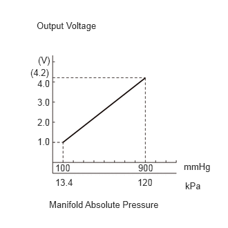
The manifold absolute pressure sensor monitors the absolute pressure inside the intake manifold (default is 0 kPa (0 mmHg, 0 in.Hg)). As a result the ECM controls the air-fuel ratio at the proper level under any driving conditions, and fuel control accuracy is not influenced by fluctuations in the atmospheric pressure due to factors such as high altitude, etc.
| DTC No. | Detection Item | DTC Detection Condition | Trouble Area | MIL | Memory |
|---|---|---|---|---|---|
| P0105 | Manifold Absolute Pressure / Barometric Pressure Circuit | Open or short in manifold absolute pressure sensor circuit for 0.5 seconds or more
(1 trip detection logic) |
·
Open or short in manifold absolute pressure sensor circuit ·
Manifold absolute pressure sensor ·
ECM |
Comes on | DTC stored |
- HINT:
-
If the ECM sets DTC P0105, it enters fail-safe mode, as follows, to allow the vehicle to be driven temporarily.
- ·
Determines the necessary intake manifold pressure, according to the engine speed and throttle valve angle (when the throttle position sensor is working properly).
·Fixes the intake manifold pressure at a preset value (when the throttle position sensor is malfunctioning).
·Performs fuel-cut when the engine speed is at a preset value or more.
-
When DTC P0105 is detected, check the intake manifold pressure by entering the following menus on the intelligent tester or Techstream: Powertrain / Engine / Data List / MAP.
Reference: Intake Manifold Pressure Malfunction Approximately 0 kPa Short in PIM circuit 120 kPa (900 mmHg, 35.4 in.Hg) or more ·Open or short in VCPM circuit
·Open in PIM circuit
·Open in E2PM circuit
- Powertrain > Engine > Data List
-
Tester Display MAP - 50003 206 31
WIRING DIAGRAM
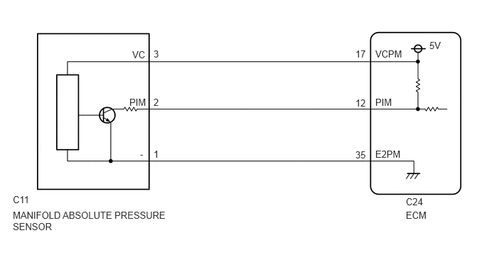
CAUTION / NOTICE / HINT
- HINT:
-
Read freeze frame data using the intelligent tester or Techstream. Freeze frame data record the engine condition when malfunctions are detected. When troubleshooting, freeze frame data can help determine if the vehicle was moving or stationary, if the engine was warmed up or not, if the air-fuel ratio was lean or rich, and other data, from the time the malfunction occurred.
PROCEDURE
Connect the intelligent tester or Techstream to the DLC3.
Turn the ignition switch to ON.
Turn the intelligent tester or Techstream on.
Enter the following menus: Powertrain / Engine / Data List / MAP.
- Powertrain > Engine > Data List
-
Tester Display MAP - 50003 206 31
Read the value.
- Standard:
Same value as the actual atmospheric pressure.
- Result:
Proceed to OK NG
OK
NG
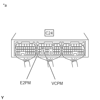
| *a | Component with harness connected
(ECM) |
Turn the ignition switch to ON.
Measure the voltage according to the value(s) in the table below.
- Standard Voltage:
Tester Connections Switch Condition Specified Conditions C24-17 (VCPM) - C24-35 (E2PM) Ignition switch ON 4.5 to 5.5 V
- Result:
Result Proceed to OK A NG (for LHD) B NG (for RHD) C
A
B
C
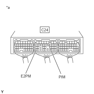
| *a | Component with harness connected
(ECM) |
Turn the ignition switch to ON.
Measure the voltage according to the value(s) in the table below.
- Standard Voltage:
Tester Connections Sensor Condition Specified Conditions C24-12 (PIM) - C24-35 (E2PM) Sensor air released 3.1 to 4.1 V
- Result:
Result Proceed to NG A OK (for LHD) B OK (for RHD) C
A
B
C
Disconnect the manifold absolute pressure sensor connector.
Disconnect the ECM connector.
Measure the resistance according to the value(s) in the table below.
- Standard Resistance (Check for Open):
Tester Connections Condition Specified Conditions C11-2 (PIM) - C24-12 (PIM) Always Below 1 Ω C11-3 (VC) - C24-17 (VCPM) Always Below 1 Ω C11-1 (-) - C24-35 (E2PM) Always Below 1 Ω
- Standard Resistance (Check for Short):
Tester Connections Condition Specified Conditions C11-2 (PIM) or C24-12 (PIM) - Body ground Always 10 kΩ or higher C11-3 (VC) or C24-17 (VCPM) - Body ground Always 10 kΩ or higher C11-1 (-) or C24-35 (E2PM) - Body ground Always 10 kΩ or higher
Reconnect the manifold absolute pressure sensor connector.
Reconnect the ECM connector.
- Result:
Proceed to OK NG
OK
NG