3SZ-VE ENGINE MECHANICAL ENGINE UNIT INSTALLATION
PROCEDURE

 19500
1.INSTALL IGNITION COIL ASSEMBLY
16507
2.INSTALL RADIATOR PIPE SUB-ASSEMBLY
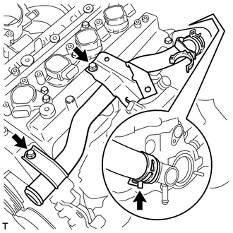
Connect the No. 4 radiator hose.
Install the radiator pipe sub-assembly with the 2 bolts.
- Torque:
- 7.5 N*m (77 kgf*cm, 66 in.*lbf)
12312
3.INSTALL NO. 2 FRONT ENGINE MOUNTING BRACKET
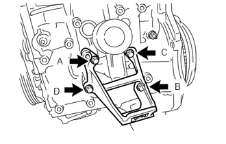
Temporarily tighten the bolt A.
Tighten the bolts in the following order: B, C, D and A.
- Torque:
- 18 N*m (184 kgf*cm, 13 ft.*lbf)
12311
4.INSTALL NO. 1 FRONT ENGINE MOUNTING BRACKET RH
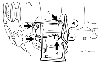
Temporarily tighten the bolt A.
Tighten the bolts in the following order: B, C, D and A.
- Torque:
- 37 N*m (377 kgf*cm, 27 ft.*lbf)
89615
5.INSTALL KNOCK CONTROL SENSOR
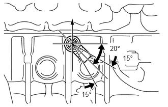
Install the knock control sensor with the nut as shown in the illustration.
- Torque:
- 20 N*m (204 kgf*cm, 15 ft.*lbf)
21591
6.INSTALL WATER BY-PASS PLATE
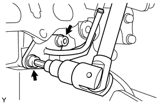
Using a 6 mm socket hexagon wrench, install the water by-pass plate with the 2 bolts.
- Torque:
- 20 N*m (204 kgf*cm, 15 ft.*lbf)
16035
7.INSTALL WATER HOSE JOINT
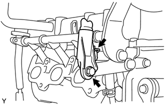
Connect No. 3 water by-pass hose to the water hose joint.
Install the water hose joint with the bolt.
- Torque:
- 7.5 N*m (77 kgf*cm, 66 in.*lbf)
17111
8.INSTALL INTAKE MANIFOLD
23291
9.INSTALL INJECTOR VIBRATION INSULATOR
23250
10.INSTALL FUEL INJECTOR ASSEMBLY
23807
11.INSTALL FUEL DELIVERY PIPE SUB-ASSEMBLY
22267
12.INSTALL THROTTLE BODY BRACKET
Install the throttle body bracket with the 2 bolts.
- Torque:
- 21 N*m (214 kgf*cm, 16 ft.*lbf)
22210
13.INSTALL THROTTLE BODY ASSEMBLY
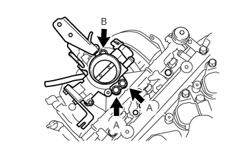
Install the throttle body assembly with the 3 bolts.
- Torque:
- Bolt A : 21 N*m (214 kgf*cm, 16 ft.*lbf)
- Torque:
- Bolt B : 7.5 N*m (77 kgf*cm, 66 in.*lbf)
16100
14.INSTALL ENGINE WATER PUMP ASSEMBLY
Install a new gasket, then install the engine water pump assembly with the 2 nuts and 3 bolts.
- Torque:
- 9.0 N*m (92 kgf*cm, 80 in.*lbf)
16173
15.INSTALL WATER PUMP PULLEY
Using SST, hold the water pump pulley.
- SST
- 09960-10010 (09962-01000, 09963-00600)
Install the water pump pulley with the 3 bolts.
- Torque:
- 12 N*m (122 kgf*cm, 9 ft.*lbf)
16603A
16.INSTALL NO. 1 IDLER PULLEY SUB-ASSEMBLY
16604B
17.INSTALL NO. 2 IDLER PULLEY SUB-ASSEMBLY
11301K
18.INSTALL CRANKSHAFT POSITION SENSOR
Install the crankshaft position sensor with the bolt.
- Torque:
- 7.5 N*m (77 kgf*cm, 66 in.*lbf)
89422A
19.INSTALL ENGINE COOLANT TEMPERATURE SENSOR
Install a new gasket onto the engine coolant temperature sensor.
Using SST, install the engine coolant temperature sensor.
- SST
- 09817-33190
- Torque:
- 20 N*m (204 kgf*cm, 15 ft.*lbf)
11101E
20.INSTALL CAMSHAFT POSITION SENSOR
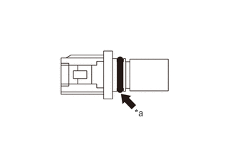
| *a | Apply a light coat of engine oil |
Apply a light coat of engine oil to the O-ring, then install the camshaft position sensor with the bolt.
- Torque:
- 7.5 N*m (77 kgf*cm, 66 in.*lbf)
- NOTICE:
-
Make sure that the O-ring is not cracked or jammed when installing.
21.INSTALL ENGINE WIRE
88431
22.INSTALL NO. 1 COMPRESSOR MOUNTING BRACKET (for LHD)
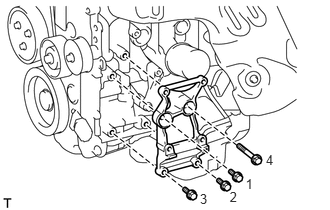
Install the No. 1 compressor mounting bracket with the 4 bolts.
- Torque:
- 28 N*m (288 kgf*cm, 21 ft.*lbf)
- HINT:
-
Tighten the bolts in the order shown in the illustration.
22268
23.INSTALL NO. 2 THROTTLE BODY BRACKET
Install the No. 2 throttle body bracket with the 2 bolts.
- Torque:
- 7.5 N*m (77 kgf*cm, 66 in.*lbf)
12262
24.INSTALL NO. 2 VENTILATION HOSE
Install the No. 2 ventilation hose.
12261
25.INSTALL VENTILATION HOSE
Install the ventilation hose.
16331A
26.INSTALL THERMOSTAT
16321
27.INSTALL WATER INLET
Install the water inlet with the bolt and nut.
- Torque:
- 9.0 N*m (92 kgf*cm, 80 in.*lbf)
Install the wiring harness clamp bracket with the bolt.
- Torque:
- 9.0 N*m (92 kgf*cm, 80 in.*lbf)
16322
28.INSTALL WATER INLET PIPE
Connect the No. 3 radiator hose to the water inlet pipe.
Install the water inlet pipe with the 2 bolts.
- Torque:
- 18 N*m (184 kgf*cm, 13 ft.*lbf)
29.INSTALL FUEL TUBE SUB-ASSEMBLY
30.INSTALL NO. 2 FUEL PIPE CLAMP
16267
31.INSTALL NO. 3 WATER BY-PASS HOSE (w/ Heater)
Connect the No. 1 fuel hose.
Connect the No. 3 water by-pass hose and No. 2 water by-pass hose.
16261
32.INSTALL WATER BY-PASS HOSE (w/o Heater)
Connect the water by-pass hoses.
16261
33.INSTALL WATER BY-PASS HOSE (w/ Heater)
Connect the 2 water by-pass hoses.
17141
34.INSTALL EXHAUST MANIFOLD
17118
35.INSTALL MANIFOLD STAY
17167
36.INSTALL NO. 1 EXHAUST MANIFOLD HEAT INSULATOR