K3-VE LUBRICATION OIL PUMP REMOVAL
PROCEDURE

 1.REMOVE ENGINE ASSEMBLY
16507
2.REMOVE RADIATOR PIPE SUB-ASSEMBLY
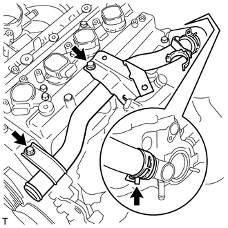
Disengage the hose clamp.
Remove the 2 bolts and the radiator pipe sub-assembly.
19500
3.REMOVE IGNITION COIL ASSEMBLY
11201
4.REMOVE CYLINDER HEAD COVER SUB-ASSEMBLY
11213
5.REMOVE CYLINDER HEAD COVER GASKET
Remove the cylinder head cover gasket from the cylinder head cover sub-assembly.
15330
6.REMOVE CAM TIMING OIL CONTROL VALVE ASSEMBLY
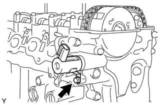
Remove the bolt, then remove the cam timing oil control valve.
16173
7.REMOVE WATER PUMP PULLEY
16630D
8.REMOVE IDLER PULLEY ASSEMBLY
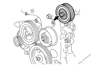
Remove the bolt and the idler pulley assembly.
16631B
9.REMOVE IDLER PULLEY BRACKET
Remove the bolt and the idler pulley bracket.
16603A
10.REMOVE NO. 1 IDLER PULLEY SUB-ASSEMBLY
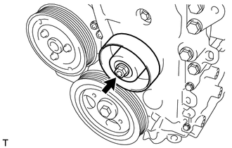
Remove the nut, No. 1 idler pulley sub-assembly and idler pulley spacer.
13471
11.REMOVE CRANKSHAFT PULLEY
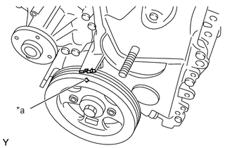
| *a | Timing Mark |
Turn the crankshaft clockwise, then align the timing mark of the crankshaft pulley with the indicator of the timing chain cover.
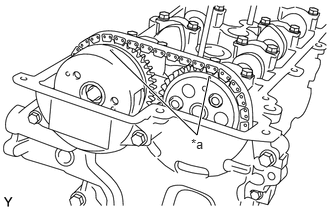
| *a | Matchmark |
Check that the matchmarks of the camshaft timing sprocket are facing upward.
If not, turn the crankshaft 1 revolution so they face upward (No. 1 cylinder at TDC/ compression).
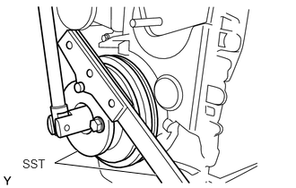
Using SST, remove the crankshaft pulley.
- SST
- 09330-00021
09213-54015 (91651-60855)
12101
12.REMOVE OIL PAN SUB-ASSEMBLY
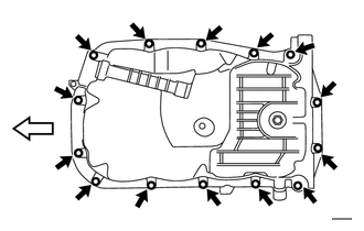

|
Engine Front |
Remove the 11 bolts and 3 nuts.
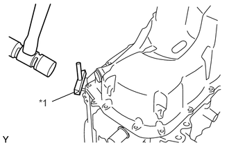
| *1 | Oil Pan Seal Cutter |
Using oil pan seal cutter, remove the oil pan sub-assembly from the cylinder block.
11302
13.REMOVE TIMING CHAIN COVER SUB-ASSEMBLY
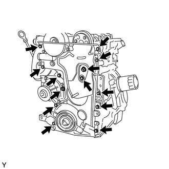
Remove the 11 bolts and 2 nuts, then remove the timing chain cover sub-assembly.
11302A
14.REMOVE TIMING CHAIN COVER OIL SEAL
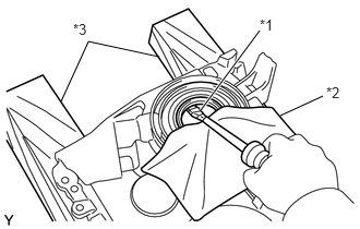
| *1 | Protective Tape |
| *2 | Piece of Cloth |
| *3 | Wooden Block |
Using a screwdriver with its tip wrapped in protective tape, remove the timing chain cover oil seal.
19315
15.REMOVE NO. 1 CRANKSHAFT POSITION SENSOR PLATE
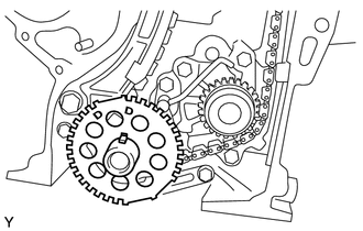
Remove the No. 1 crankshaft position sensor plate from the crankshaft.
13545
16.REMOVE CHAIN TENSIONER PLUNGER
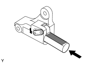
Move the stopper plate of the tensioner downward, then push the chain tensioner plunger to the end, keeping it unlocked.
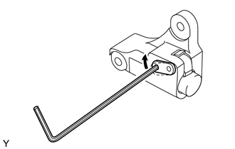
Move the stopper plate upward and lock it. Align the holes of the stopper plate and tensioner, then insert a 2.5 mm (0.098 in.) diameter hexagon wrench.
Remove the bolt and nut, then remove the chain tensioner plunger.
13506
17.REMOVE CHAIN SUB-ASSEMBLY
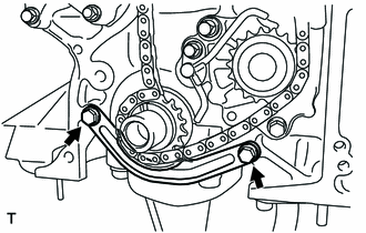
Remove the 2 bolts and the No. 2 timing chain guide.
Remove the chain sub-assembly.
13566B
18.REMOVE TIMING CHAIN GUIDE
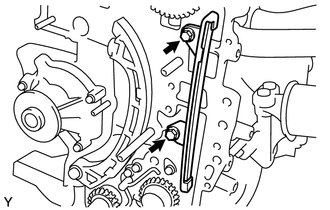
Remove the 2 bolts and the timing chain guide.
13591
19.REMOVE TIMING CHAIN TENSION ARM
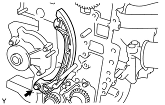
Remove the bolt and the timing chain tension arm.
15708
20.REMOVE NO. 1 OIL NOZZLE SUB-ASSEMBLY
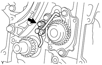
Remove the bolt and the No. 1 oil nozzle sub-assembly.
15100
21.REMOVE OIL PUMP ASSEMBLY
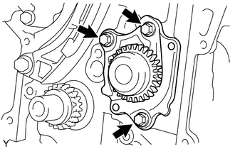
Remove the 3 bolts and the oil pump assembly.
- NOTICE:
-
Do not drop the oil pump driven rotor as it is not fixed onto the oil pump assembly.