A4Q AUTOMATIC TRANSMISSION / TRANSAXLE AUTOMATIC TRANSMISSION SYSTEM P0748 Pressure Control Solenoid "A" Electrical (Shift Solenoid Valve SL1)
DESCRIPTION
Shifting from 1st to 4th is performed in combination with ON and OFF operation of the shift solenoid valves SL1, SL2, SL3, SL, DSU and SR which is controlled by the TCM. If an open or short circuit occurs in any of the shift solenoid valves, the TCM controls the remaining normal shift solenoid valves to allow the vehicle to be operated smoothly (Fail-safe function).
| DTC No. | Detection Item | DTC Detection Condition | Trouble Area | MIL | Warning Indicate | Memory |
|---|---|---|---|---|---|---|
| P0748 | Pressure Control Solenoid "A" Electrical (Shift Solenoid Valve SL1) | When electricity is applied to the shift solenoid valve SL1, the condition that the current does not flow at all or overflow continues.
(1 trip detection logic) |
·
Open or short in shift solenoid valve SL1 circuit ·
Shift solenoid valve SL1 ·
TCM |
Come on | Blinks | DTC stored |
MIL:"Comes on" means the MIL (Malfunction IndicatorLamp) illuminates.
Memory:"DTC stored" means the TCM stores the trouble code if the ECU detects the DTC detection condition.
WIRING DIAGRAM
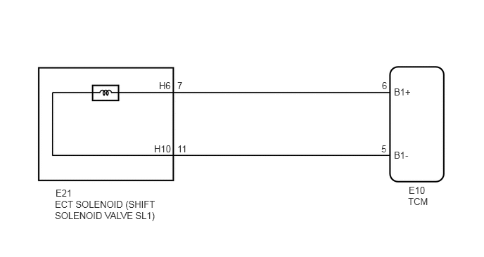
PROCEDURE
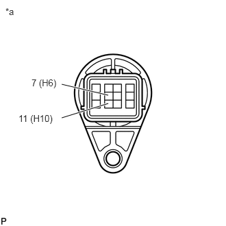
| *a | Front view of wire harness connector
(to Solenoid wire) |
Disconnect the E21 solenoid wire connector.
Measure the resistance according to the value(s) in the table below.
- Standard resistance:
Tester Connection Condition Specified Condition 7 (H6) - 11 (H10) 20°C (68°F) 5.0 to 5.6 Ω 7 (H6) - Body ground Always 10 kΩ or higher 11 (H10) - Body ground Always 10 kΩ or higher
Reconnect the E21 solenoid wire connector.
- Result:
proceed to OK NG
OK
NG
Disconnect the E10 TCM connector.
Measure the resistance according to the value(s) in the table below.
- Standard resistance:
Tester Connection Condition Specified Condition E10-6 (B1+) - E10-5 (B1-) 20°C (68°F) 5.0 to 5.6 Ω E10-6 (B1+) - Body ground Always 10 kΩ or higher E10-5 (B1-) - Body ground Always 10 kΩ or higher
Reconnect the E10 TCM connector.
- Result:
proceed to OK NG
OK
NG
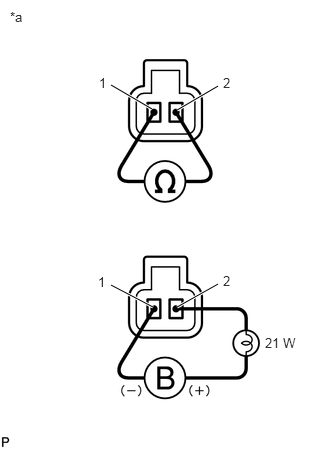
| *a | Component without harness connected
(Shift Solenoid Valve SL1) |
Remove the shift solenoid valve SL1.
Measure the resistance according to the value(s) in the table below.
- Standard resistance:
Tester Connection Condition Specified Condition 1 - 2 20°C (68°F) 5.0 to 5.6 Ω
Connect the positive (+) lead with a 21 W bulb to terminal 2 and the negative (-) lead to terminal 1 of the solenoid valve connector, then check the movement of the valve.
- NOTICE:
- ·
Never directly apply battery voltage to the solenoid valve connector (Do not allow a current of 1 A or more to flow). Perform the operation check via the specified bulb (resistance).
·If a current of 1 A or more flows, the characteristic of the solenoid valve changes.
- OK:
The solenoid valve makes an operating sound.
- Result:
proceed to OK NG
OK
NG