M5S MANUAL TRANSMISSION / TRANSAXLE INPUT SHAFT REASSEMBLY
PROCEDURE

 33380
1.INSTALL NO. 3 SYNCHRONIZER HUB ASSEMBLY
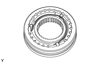
Coat the No. 3 hub sleeve with manual transmission gear oil, and install it onto the No. 3 clutch hub.
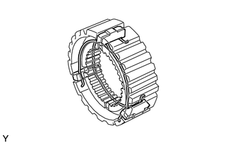
Install the 3 synchromesh shifting keys and 2 synchromesh shifting key springs.
- NOTICE:
-
Install the synchromesh shifting key springs so that the openings of the right and left springs are not aligned.
33370
2.INSTALL NO. 2 SYNCHRONIZER HUB ASSEMBLY
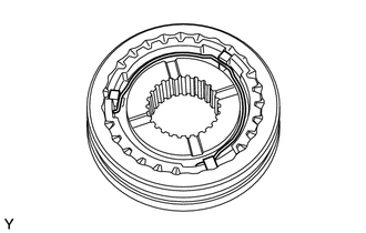
Coat the No. 2 hub sleeve with manual transmission gear oil, and install it onto the No. 2 clutch hub.
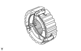
Install the 3 synchromesh shifting keys and 2 synchromesh shifting key springs.
- NOTICE:
-
Install the synchromesh shifting key springs so that the openings of the right and left springs are not aligned.
3.INSTALL INPUT SHAFT FRONT BEARING
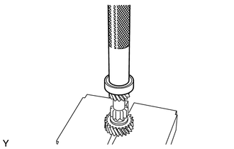
Using SST and a press, install the input shaft front bearing.
- SST
- 09612-22011
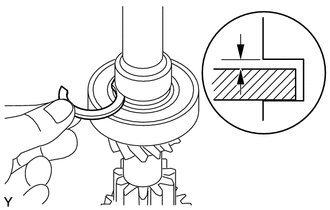
| *1 | Snap Ring |
Select a new snap ring that allows the minimum amount of axial play.
- Standard clearance:
0 mm (0 in.)
- Maximum clearance:
0.16 mm (0.0063 in.)
| Part No. | Thickness mm (in.) | Part No. | Thickness mm (in.) |
|---|---|---|---|
| 9004A-52046 | 2.06 (0.0811) | 9004A-52050 | 1.90 (0.0748) |
| 9004A-52047 | 2.02 (0.0795) | 9004A-52051 | 1.86 (0.0732) |
| 9004A-52048 | 1.98 (0.0780) | 9004A-52052 | 1.82 (0.0717) |
| 9004A-52049 | 1.94 (0.0764) | 9004A-52053 | 1.78 (0.0701) |
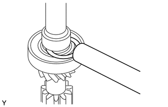
Using a brass bar and a hammer, install the snap ring onto the input shaft.
33336
4.INSTALL 5TH GEAR
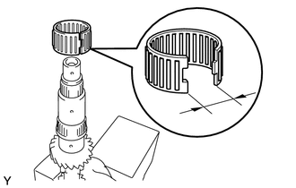
Coat the split type needle roller bearing with manual transmission gear oil, and install it onto the input shaft.
- NOTICE:
-
Do not widen the opening of the split type needle roller bearing 36 mm (1.42 in.) or more.
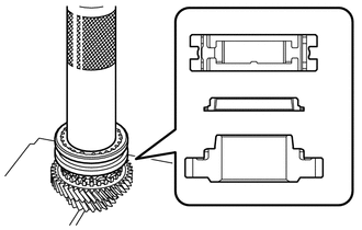
| *1 | 5th Gear |
| *2 | No. 1 Synchronizer Ring |
| *3 | No. 3 Synchronizer Hub Assembly |
Using SST and a press, install the 5th gear, No. 1 synchronizer ring and No. 3 synchronizer hub assembly.
- SST
- 09608-06041
- NOTICE:
-
Paying attention to the proper position, fit the synchromesh shifting key into the groove of the synchronizer ring.
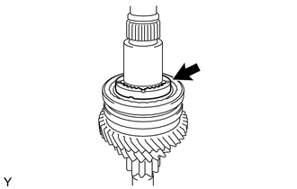
Coat the hub sleeve stopper with manual transmission gear oil and install it onto the input shaft.
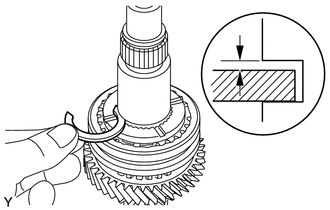
| *1 | Snap Ring |
Select a new snap ring that allows the minimum amount of axial play.
- Standard clearance:
0 mm (0 in.)
- Maximum clearance:
0.16 mm (0.0063 in.)
| Part No. | Thickness mm (in.) | Part No. | Thickness mm (in.) |
|---|---|---|---|
| 9004A-52038 | 2.06 (0.0811) | 9004A-52042 | 1.90 (0.0748) |
| 9004A-52039 | 2.02 (0.0795) | 9004A-52043 | 1.86 (0.0732) |
| 9004A-52040 | 1.98 (0.0780) | 9004A-52044 | 1.82 (0.0717) |
| 9004A-52041 | 1.94 (0.0764) | 9004A-52045 | 1.78 (0.0701) |
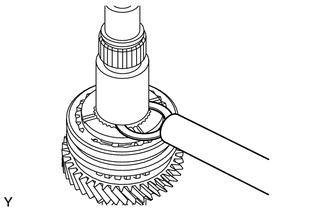
Using a brass bar and a hammer, install the snap ring onto the input shaft.
33369B
5.INSTALL NO. 4 SYNCHRONIZER RING
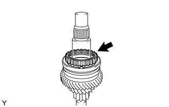
Coat the No. 4 synchronizer ring with manual transmission gear oil and install it onto the input shaft.
33333
6.INSTALL 3RD GEAR SUB-ASSEMBLY
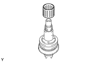
Coat the needle roller bearing with manual transmission gear oil, and install it onto the input shaft.
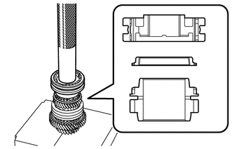
| *1 | 3rd Gear Sub-Assembly |
| *2 | No. 1 Synchronizer Ring |
| *3 | No. 2 Synchronizer Hub Assembly |
Using SST and a press, install the 3rd gear subassembly, No. 1 synchronizer ring and No. 2 synchronizer hub assembly.
- SST
- 09612-22011
- NOTICE:
-
Paying attention to the proper position, fit the synchromesh shifting key into the groove of the synchronizer ring.
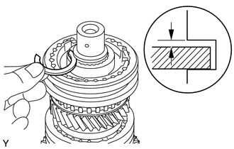
| *1 | Snap Ring |
Select a new snap ring that allows the minimum amount of axial play.
- Standard clearance:
0 mm (0 in.)
- Maximum clearance:
0.16 mm (0.0063 in.)
| Part No. | Thickness mm (in.) | Part No. | Thickness mm (in.) |
|---|---|---|---|
| 9004A-52046 | 2.06 (0.0811) | 9004A-52050 | 1.90 (0.0748) |
| 9004A-52047 | 2.02 (0.0795) | 9004A-52051 | 1.86 (0.0732) |
| 9004A-52048 | 1.98 (0.0780) | 9004A-52052 | 1.82 (0.0717) |
| 9004A-52049 | 1.94 (0.0764) | 9004A-52053 | 1.78 (0.0701) |
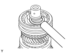
Using a brass bar and hammer, install the snap ring onto the input shaft.
33333
7.INSPECT 3RD GEAR THRUST CLEARANCE
33336
8.INSPECT 5TH GEAR THRUST CLEARANCE