AXLE AND DIFFERENTIAL REAR DIFFERENTIAL CARRIER ASSEMBLY(for K3-VE) REASSEMBLY
PROCEDURE

 41311J
1.ASSEMBLE REAR DIFFERENTIAL CASE
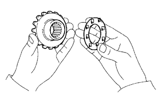
Install the rear differential side gear thrust washer onto the rear differential side gear.
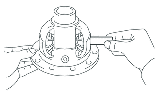
Install the rear differential side gears, pinion gears and pinion shaft onto the differential case.
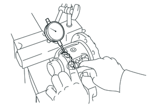
Using a dial indicator, measure the differential case backlash while holding the pinion toward the case.
- Backlash:
0 to 0.075 mm (0 to 0.0030 in.)
If the backlash is not within the specification, install 2 side gear thrust washers of a different thickness.
- Thrust washer thickness:
Thickness mm (in.) Thickness mm (in.) 1.10 (0.0433) 1.25 (0.0492) 1.15 (0.0453) 1.30 (0.0512) 1.20 (0.0472) 1.35 (0.0531)
2.INSTALL DIFFERENTIAL RING GEAR
Clean the contact surfaces of the differential case and ring gear.
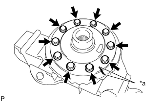
| *a | Matchmark |
Align the matchmarks on the ring gear with those of the differential case.
- NOTICE:
- ·
Align the bolt holes in the differential case with the screw holes in the differential ring gear.
·If it is difficult to install the ring gear, wrap the gear in a cloth to protect it, and tap the outer edge of the gear evenly with a plastic hammer.
Temporarily install the 10 bolts.
Install the 10 bolts by diametrically tightening the bolts uniformly in several steps.
- Torque:
- 97 N*m (989 kgf*cm, 72 ft.*lbf)
41301A
3.INSTALL REAR DIFFERENTIAL CASE BEARING
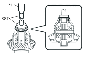
| *1 | Press |
Using SST and a press, press the bearing RH onto the differential case.
- SST
- 09950-60010 (09951-00500)
09950-70010 (09951-07150)
41301A
4.INSTALL REAR DIFFERENTIAL CASE BEARING
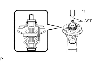
| *1 | Press |
Using SST and a press, press the bearing LH onto the differential case.
- SST
- 09950-60010 (09951-00490, 09951-00500)
09950-70010 (09951-07150)
5.INSPECT DIFFERENTIAL RING GEAR RUNOUT
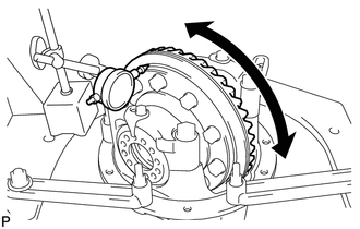
Install the differential case on the carrier, and install the 2 adjusting nuts so that there is no play in the bearing.
Install the 2 bearing caps with the 4 bolts.
- Torque:
- 84 N*m (852 kgf*cm, 62 ft.*lbf)
Using a dial indicator, measure the runout of the ring gear.
- Maximum runout:
0.10 mm (0.0039 in.)
Remove the 2 bearing caps, 2 adjusting nuts and the differential case.
41201B
6.INSTALL REAR DRIVE PINION FRONT TAPERED ROLLER BEARING
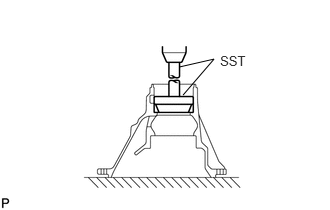
Using SST and a press, press in the roller bearing (outer) to the carrier.
- SST
- 09950-60010 (09951-00620)
09950-70010 (09951-07150)
41201D
7.INSTALL REAR DIFFERENTIAL DRIVE PINION PLATE WASHER
Install the rear differential drive pinion washer that was removed during the disassembly.
- NOTICE:
-
Inspect the rear differential drive pinion washer.
-
If there is any wear, scratches or other defects, install a new rear differential drive pinion washer of the same thickness.
41201A
8.INSTALL REAR DRIVE PINION REAR TAPERED ROLLER BEARING
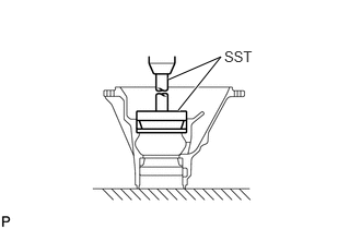
Using SST and a press, press the roller bearing (outer) into the carrier.
- SST
- 09950-60020 (09951-00720)
09950-70010 (09951-07150)
41201A
9.INSTALL REAR DRIVE PINION REAR TAPERED ROLLER BEARING
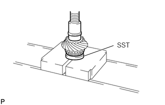
Install the plate washer onto the drive pinion.
- HINT:
-
First fit a washer with the same thickness as the removed washer, and then check the tooth contact pattern. Replace the washer with one of a different thickness if necessary.
Using SST and a press, press the roller bearing (inner) onto the drive pinion.
- SST
- 09506-30012
10.ADJUST DIFFERENTIAL DRIVE PINION PRELOAD
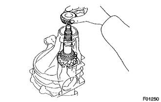
Install the drive pinion and rear drive pinion front tapered roller bearing.
- HINT:
-
Assemble the spacer and oil seal after adjusting the gear contact pattern.
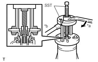
| *a | Turn |
| *b | Hold |
Using SST, install the companion flange.
- SST
- 09950-30012 (09951-03010, 09953-03010, 09954-03010, 09956-03020, 09955-03030)
- NOTICE:
-
Before using SST (center bolt), apply hypoid gear oil to its threads and tip.
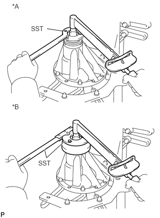
| *A | for Manual Transmission |
| *B | for Automatic Transmission |
Using SST to hold the companion flange in place, adjust the drive pinion preload by tightening a new companion flange nut.
- NOTICE:
-
As there is no spacer, torque a little at a time. Be careful not to overtighten the nut.
for Manual Transmission:
- SST
- 09330-87301
for Automatic Transmission:
- SST
- 09330-00021
09950-30012 (09955-03030)
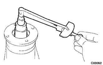
Using a torque wrench, measure the preload.
- Preload (at starting):
Bearing Standard New bearing 0.57 to 0.96 N*m (5.8 to 9.8kgf*cm, 5.0 to 8.5 in.*lbf) Used bearing 0.49 to 0.78 N*m (5.0 to 8.0 kgf*cm, 4.5 to 7.0 in.*lbf)
- NOTICE:
-
For a more accurate measurement, rotate the bearing forward and backward several times before measuring.
- HINT:
-
Make a note of the values for the below total preload inspection procedure.
41311J
11.INSTALL REAR DIFFERENTIAL CASE
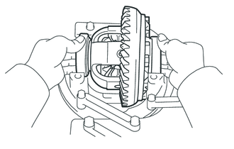
Place the 2 bearing outer races on their respective bearings.
- HINT:
-
Do not interchange the right and left races.
41315
12.INSTALL REAR DIFFERENTIAL BEARING ADJUSTING NUT
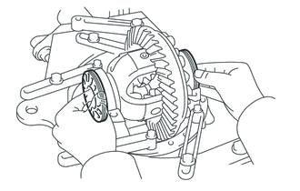
Install the 2 adjusting nuts onto the carrier, making sure the nuts are threaded properly.
13.INSPECT AND ADJUST DIFFERENTIAL RING GEAR AND DIFFERENTIAL DRIVE PINION BACKLASH
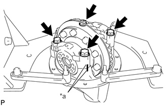
| *a | Matchmark |
Align the matchmarks on the cap and carrier.
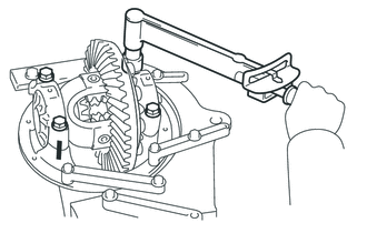
Install the right and left bearing caps with the 4 bolts.
- Torque:
- 84 N*m (857 kgf*cm, 62 ft.*lbf)
If the bearing cap does not fit tightly on the carrier, the adjusting nuts are not threaded properly.
- HINT:
-
Reinstall the adjusting nuts if necessary.
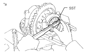
| *a | LH Side |
Loosen the 4 bearing cap bolts to the point where the adjusting nuts can be turned using SST.
Using SST, torque the adjusting nut on the ring gear side until the ring has a backlash of about 0.15 mm (0.006 in.).
- SST
- 09504-00011
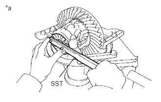
| *a | RH Side |
While turning the ring gear, use SST to fully tighten the adjusting nut on the drive pinion side. After the bearings have settled, loosen the adjusting nut on the drive pinion side.
Using SST, tighten the adjusting nut 1 to 2 notches from the 0 preload position.
- SST
- 09504-00011
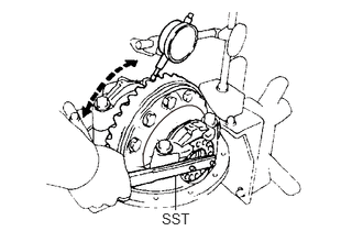
Using a dial indicator, adjust the ring gear backlash until it is within the specification.
- Standard backlash:
0.08 to 0.13 mm (0.0031 to 0.0052 in.)
- HINT:
- ·
The backlash is adjusted by turning the left and right adjusting nuts an equal amount. For example, loosen the nut on the right side one notch and loosen the nut on the left side one notch.
·Perform the measurement at 3 or more positions around the circumference of the ring gear.
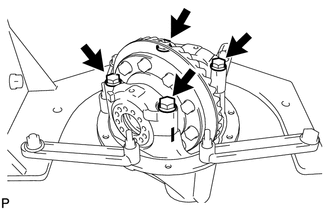
Torque the bearing cap bolts.
- Torque:
- 84 N*m (852 kgf*cm, 62 ft.*lbf)
14.INSPECT TOTAL PRELOAD
Using a torque wrench, measure the preload with the teeth of the drive pinion and ring gear in contact.
- Total preload (at starting):
Drive pinion preload plus 0.20 to 0.39 N*m (2.0 to 4.0 kgf*cm, 1.77 to 3.45 in.*lbf)
If necessary, disassemble and inspect the differential.
15.INSPECT TOOTH CONTACT BETWEEN RING GEAR AND DRIVE PINION
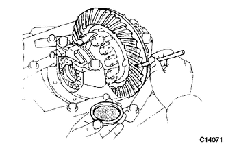
Coat 3 or 4 teeth at 3 different positions on the ring gear with prussian blue.
Hold the companion flange firmly in place and rotate the ring gear in both directions.
Inspect the tooth contact pattern.
If the teeth are not engaged properly, use the following chart to select a proper washer.
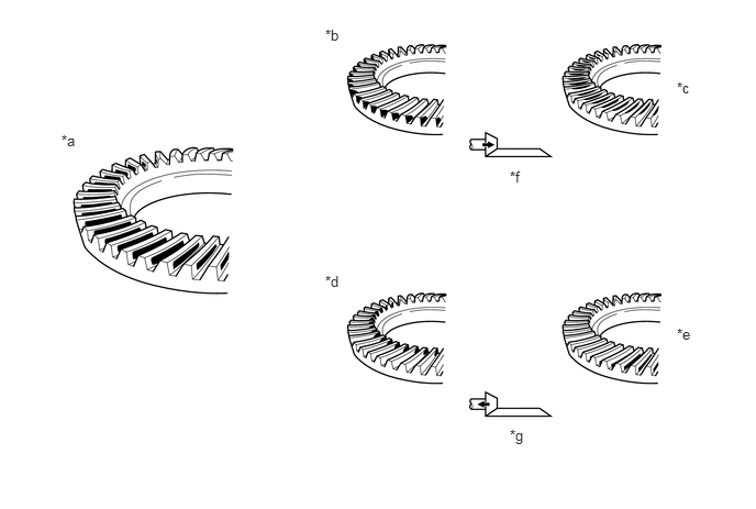
| *a | Proper Contact | *b | Heel Contact |
| *c | Face Contact | *d | Toe Contact |
| *e | Frank Contact | *f | Select an adjusting washer that brings the drive pinion closer to the ring gear. |
| *g | Select an adjusting washer that shifts the drive pinion away from the ring gear. | - | - |
- Plate Washer Thickness:
Thickness mm (in.) Thickness mm (in.) 0.29 (0.0114) 0.50 (0.0197) 0.32 (0.0126) 0.53 (0.0209) 0.35 (0.0138) 0.56 (0.0220) 0.38 (0.0150) 0.59 (0.0232) 0.41 (0.0161) 0.62 (0.0244) 0.44 (0.0173) 0.65 (0.0256) 0.47 (0.0185) -
16.REMOVE REAR DRIVE PINION NUT
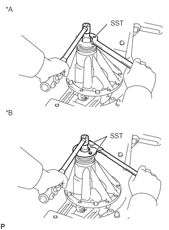
| *A | for Manual Transmission |
| *B | for Automatic Transmission |
Using SST to hold the companion flange in place, remove the nut.
for Manual Transmission:
- SST
- 09330-87301
for Automatic Transmission:
- SST
- 09330-00021
09950-30012 (09955-03030)
41204
17.REMOVE REAR DRIVE PINION COMPANION FLANGE SUB-ASSEMBLY
41201B
18.REMOVE REAR DRIVE PINION FRONT TAPERED ROLLER BEARING
41231
19.INSTALL REAR DIFFERENTIAL DRIVE PINION BEARING SPACER
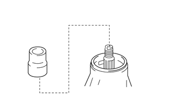
Install the bearing spacer onto the drive pinion.
- NOTICE:
-
Install the spacer so that the larger diameter end is facing the rear of the vehicle.
41201E
20.INSTALL REAR DIFF DRIVE PINION SPACER FRONT ADJUST SHIM
Install the drive pinion spacer front adjust shim that was removed during the disassembly.
- NOTICE:
-
Inspect the drive pinion spacer front adjust shim. If there is any wear, scratches or other defects, install a new drive pinion spacer front adjust shim of the same thickness.
41201B
21.INSTALL REAR DRIVE PINION FRONT TAPERED ROLLER BEARING
41204
22.INSTALL REAR DRIVE PINION COMPANION FLANGE SUB-ASSEMBLY
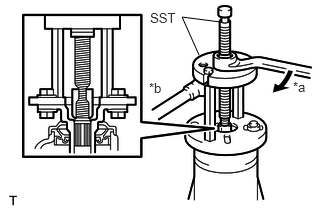
| *a | Turn |
| *b | Hold |
Using SST, install the companion flange onto the drive pinion.
- SST
- 09950-30012 (09951-03010, 09953-03010, 09955-03030, 09956-03020, 09954-03010)
- NOTICE:
-
Before using SST (center bolt), apply hypoid gear oil to its threads and tip.
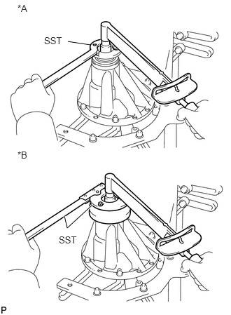
| *A | for Manual Transmission |
| *B | for Automatic Transmission |
Using SST to hold the flange, torque the nut.
- Torque:
- 157 N*m (1600 kgf*cm, 116 ft.*lbf)
for Manual Transmission:
- SST
- 09330-87301
for Automatic Transmission:
- SST
- 09330-00021 09950-30012 (09955-03030)
23.INSPECT DRIVE PINION PRELOAD
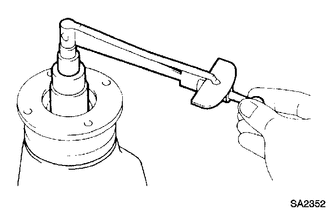
Using a torque wrench, measure the preload of the backlash between the drive pinion and ring gear.
- Preload (at starting):
Bearing Standard New Bearing 0.57 to 0.96 N*m (5.8 to 9.8 kgf*cm, 5.0 to 8.5 in.*lbf) Used Bearing 0.49 to 0.78 N*m (5.0 to 8.0 kgf*cm, 4.5 to 7.0 in.*lbf)
- NOTICE:
-
For a more accurate measurement, rotate the bearing forward and backward several times before measuring.
If the starting torque is not within the specified range, select a rear differential drive pinion spacer front adjust shim according to the table below and adjust the starting torque.
- Adjust shim Thickness:
Thickness mm (in.) Thickness mm (in.) 1.65 (0.0650) 2.10 (0.0827) 1.70 (0.0670) 2.15 (0.0846) 1.75 (0.0689) 2.20 (0.0866) 1.80 (0.0709) 2.25 (0.0886) 1.85 (0.0728) 2.30 (0.0906) 1.90 (0.0748) 2.35 (0.0925) 1.95 (0.0768) 2.40 (0.0945) 2.00 (0.0787) 2.45 (0.0965) 2.05 (0.0807) -
- HINT:
-
Make a note of the values for the below total preload inspection procedure.
24.INSPECT TOTAL PRELOAD
Using a torque wrench, measure the preload with the teeth of the drive pinion and ring gear in contact.
- Total preload (at starting):
Drive pinion preload plus 0.20 to 0.39 N*m (2.0 to 4.0 kgf*cm, 1.77 to 3.45 in.*lbf)
If necessary, disassemble and inspect the differential.
25.REMOVE REAR DRIVE PINION NUT
41204
26.REMOVE REAR DRIVE PINION COMPANION FLANGE SUB-ASSEMBLY
41201C
27.INSTALL REAR DIFFERENTIAL CARRIER OIL SEAL
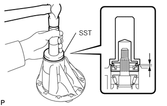
Apply MP grease to a new oil seal.
Using SST and a hammer, tap in the oil seal.
- SST
- 09554-22010
- Oil seal depth:
0 to 1.0 mm(0 to 0.039 in.)
41252
28.INSTALL REAR DIFFERENTIAL DUST DEFLECTOR
- HINT:
-
If the dust deflector has been removed, perform the installation.
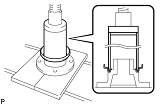
Using SST and a press, install the dust deflector.
- SST
- 09523-36010
09950-60010 (09951-00570)
- CAUTION:
-
Be careful not to damage the dust deflector.
41204
29.INSTALL REAR DRIVE PINION COMPANION FLANGE SUB-ASSEMBLY
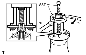
| *a | Turn |
| *b | Hold |
Using SST, install the companion flange onto the drive pinion.
- SST
- 09950-30012 (09951-03010, 09953-03010, 09954-03010, 09955-03030, 09956-03020)
- NOTICE:
-
Before using SST (center bolt), apply hypoid gear oil to its threads and tip.
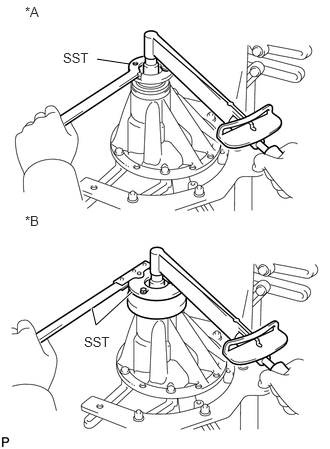
| *A | for Manual Transmission |
| *B | for Automatic Transmission |
Using SST to hold the flange, torque the nut.
- Torque:
- 157 N*m (1600 kgf*cm, 116 ft.*lbf)
for Manual Transmission:
- SST
- 09330-87301
for Automatic Transmission:
- SST
- 09330-00021
09950-30012 (09955-03030)
30.INSPECT DIFFERENTIAL RING GEAR BACKLASH
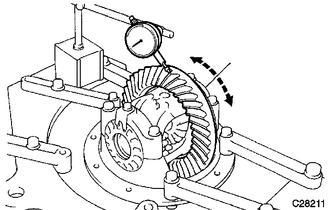
Using a dial indicator, check the backlash of the ring gear.
- Standard backlash:
0.08 to 0.13 mm (0.0031 to 0.0052 in.)
If the backlash is not as specified, adjust the side bearing preload or repair as necessary.
- HINT:
-
Perform the measurements at 3 or more positions around the circumference of the ring gear.
41204
31.INSPECT RUNOUT OF REAR DRIVE PINION COMPANION FLANGE SUB-ASSEMBLY
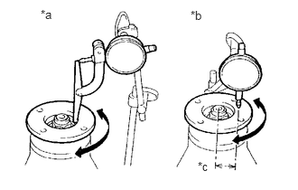
| *a | Vertical Runout |
| *b | Lateral Runout |
| *c | 30 mm (1.18 in.) |
Using a dial indicator, measure the runout of the drive pinion companion flange vertically and laterally.
- Maximum runout:
Runout Maximum Vertical runout 0.10 mm (0.0039 in.) Lateral runout 0.10 mm (0.0039 in.)
If the runout is greater than the maximum, replace the companion flange.
32.STAKE REAR DRIVE PINION NUT
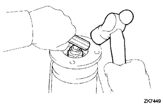
Using a chisel and hammer, stake the nut.
41316
33.INSTALL REAR DIFFERENTIAL BEARING ADJUSTING NUT LOCK
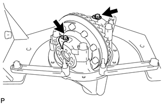
Install 2 new adjusting nut locks onto the bearing caps with the 2 bolts.
- Torque:
- 5.4 N*m (55 kgf*cm, 48 in.*lbf)
Bend the nut locks.
- HINT:
-
Perform the measurements at 3 or more positions around the circumference of the ring gear.