RM19Y0E
_54
Brake
_002992
BRAKE CONTROL / DYNAMIC CONTROL SYSTEMS
_0015137
ANTI-LOCK BRAKE SYSTEM
J
BRAKE CONTROL / DYNAMIC CONTROL SYSTEMS ANTI-LOCK BRAKE SYSTEM ECUT TERMINAL CIRCUIT
DESCRIPTION
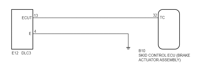
Connecting terminals ECUT and E of the DLC3 causes the skid control ECU (brake actuator assembly) to display 2-digit DTCs by flashing the ABS warning light.
WIRING DIAGRAM
5.042,1.927 7.01,2.792
1.969,0.865
10
SKID CONTROL ECU (BRAKE ACTUATOR ASSEMBLY)
5.042,1.76 5.656,2.073
0.615,0.313
10
B10
0.781,1.844 1.604,2.365
0.823,0.521
10
DLC3
0.427,1.844 0.938,2.177
0.51,0.333
10
E12
5.813,0.552 6.323,0.917
0.51,0.365
10
TC
5.563,0.469 5.99,0.792
0.427,0.323
10
32
0.792,0.563 1.438,0.906
0.646,0.344
10
ECUT
1.229,0.479 1.688,0.854
0.458,0.375
10
13
1.052,1.135 1.344,1.49
0.292,0.354
10
E
1.24,1.052 1.563,1.365
0.323,0.313
10
4
PROCEDURE
1.CHECK DLC3 TERMINAL VOLTAGE (ECUT)
2.302,0.094 2.792,0.385
0.49,0.292
1.604,0.771 1.417,0.354
true
1.844,1.427 1.844,1.792
true
1.302,0.167 1.625,0.49
0.323,0.323
10
E
1.646,1.823 2.427,2.135
0.781,0.313
10
ECUT
0.167,0.125 0.625,0.521
0.458,0.396
10
*a
2.427,0.167 2.896,0.469
0.469,0.302
10
E12
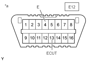
| *a | Front view of DLC3 |
a.
Turn the ignition switch to ON.
b.
Measure the voltage according to the value(s) in the table below.
- Standard voltage:
Tester Connection Specified Condition E12-13 (ECUT) - E12-4 (E) 11 to 14 V
- Result:
Proceed to OK NG
OK
END
NG
2.CHECK HARNESS AND CONNECTOR (SKID CONTROL ECU - DLC3)
2.CHECK HARNESS AND CONNECTOR (SKID CONTROL ECU - DLC3)
a.
Disconnect the skid control ECU (brake actuator assembly) connector.
b.
Measure the resistance according to the value(s) in the table below.
- Standard resistance:
Tester Connection Specified Condition B10-32 (TC) - E12-13 (ECUT) Below 1 Ω B10-32 (TC) - Body ground 10 kΩ or higher
- Result:
Proceed to OK NG
OK
3.CHECK HARNESS AND CONNECTOR (DLC3 - BODY GROUND)
NG
REPAIR OR REPLACE HARNESS OR CONNECTOR
3.CHECK HARNESS AND CONNECTOR (DLC3 - BODY GROUND)
a.
Measure the resistance according to the value(s) in the table below.
- Standard resistance:
Tester Connection Specified Condition E12-4 (E) - Body ground Below 1 Ω
- Result:
Proceed to OK NG
OK
REPLACE BRAKE ACTUATOR
NG
REPAIR OR REPLACE HARNESS OR CONNECTOR