METER / GAUGE / DISPLAY METER / GAUGE SYSTEM Tachometer Malfunction
DESCRIPTION
The combination meter assembly controls the tachometer in accordance with engine speed signals from the ECM.
WIRING DIAGRAM
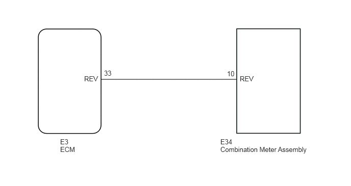
PROCEDURE
Connect the intelligent tester or Techstream to the DLC3.
Turn the ignition switch to ON.
Turn the intelligent tester or Techstream on.
Enter the following menus: Powertrain / Engine and ECT / Data List.
- Powertrain > Engine > Data List
-
Tester Display Engine Speed - 50003 206 32
According to the display on the tester, read the Data List.
- Powertrain > Engine > Data List
-
Tester Display Measurement Item Range Normal Condition Diagnostic Note Engine Speed Engine speed Min.: 0 rpm
Max.: 16383.75 rpm700 to 800 rpm: Idling -
- OK:
Engine speed displayed on the tester is approximately the same as the actual engine speed.
- Result:
Result Proceed to OK A NG (3SZ-VE) B NG (K3-VE) C
A
B
C
Click hereEngine / Hybrid System>K3-VE ENGINE CONTROL>SFI SYSTEM>HOW TO PROCEED WITH TROUBLESHOOTING
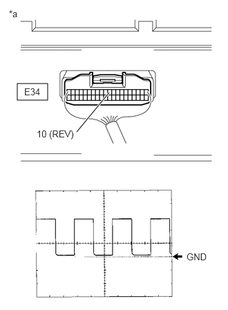
| *a | Component with harness connected
(Combination Meter Assembly) |
Check the input waveform.
Remove the combination meter assembly with the connector still connected.
Connect an oscilloscope to terminal E34-10 (REV) and body ground.
Start the engine.
Check the signal waveform according to the condition(s) in the table below.
| Item | Condition |
|---|---|
| Tool Setting | 5 V/DIV., 10 ms/DIV. |
| Vehicle Condition | Engine idle speed |
- OK:
The waveform is displayed as shown in the illustration.
- HINT:
-
As the vehicle speed increases, the cycle of the signal waveform narrows.
- Result:
Proceed to OK NG
OK
NG
Disconnect the E34 combination meter assembly connector.
Disconnect the E3 ECM connector.
Measure the resistance according to the value(s) in the table below.
- Standard Resistance (Check for Open):
Tester Connection Condition Specified Condition E34-10 (REV) - E3-33 (REV) Always Below 1 Ω
- Standard Resistance (Check for Short):
Tester Connection Condition Specified Condition E34-10 (REV) - Body ground Always 10 kΩ or higher
- Result:
Result Proceed to NG A OK (3SZ-VE) B OK (K3-VE) C
A
B
C