Home › Engine / Hybrid System › 3SZ-VE ENGINE CONTROL › SFI SYSTEM(w/o Rear Heated Oxygen Sensor) › 2014.04–2015.08
RM19Y0E _51 Engine / Hybrid System _002968 3SZ-VE ENGINE CONTROL _0014987 SFI SYSTEM(w/o Rear Heated Oxygen Sensor) C

3SZ-VE ENGINE CONTROL  SFI SYSTEM(w/o Rear Heated Oxygen Sensor)  P0530  A/C Pressure Sensor Signal  


DESCRIPTION

The air conditioning pressure sensor is attached to the high-pressure pipe block to detect an abnormal refrigerant pressure. A DTC is stored if abnormal refrigerant pressure is detected.

DTC No. Detection Item DTC Detection Condition Trouble Area MIL Memory
P0530 A/C Pressure Sensor Signal Refrigerant pressure is less than 0 MPa (0 kgf/cm2) or 3.187 MPa (32 kgf/cm2) or higher.
(1 trip detection logic)
·

Open or short in air conditioning pressure sensor circuit

·

Air conditioning pressure sensor

·

ECM


- DTC stored

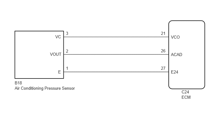
WIRING DIAGRAM

A325176E01
0.49,2.865 2.646,3.281 2.156,0.417 10 false Air Conditioning Pressure Sensor 0.49,2.688 0.854,2.896 0.365,0.208 10 false B18 5.698,1.156 6.063,1.365 0.365,0.208 10 false VCO 5.698,1.74 6.177,1.948 0.479,0.208 10 false ACAD 6.052,2.99 6.417,3.198 0.365,0.208 10 false C24 6.052,3.167 6.635,3.406 0.583,0.24 10 false ECM 5.698,2.323 6.177,2.531 0.479,0.208 10 false E24 5.365,1.031 5.844,1.24 0.479,0.208 10 false 21 5.365,1.615 5.844,1.823 0.479,0.208 10 false 26 5.365,2.198 5.844,2.406 0.479,0.208 10 false 27 2.198,1.031 2.677,1.24 0.479,0.208 10 false 3 2.198,1.625 2.677,1.833 0.479,0.208 10 false 2 2.198,2.198 2.677,2.406 0.479,0.208 10 false 1 1.844,1.146 2.323,1.354 0.479,0.208 10 false VC 1.667,1.729 2.146,1.938 0.479,0.208 10 false VOUT 1.938,2.323 2.417,2.531 0.479,0.208 10 false E

PROCEDURE

1.INSPECT AIR CONDITIONING PRESSURE SENSOR (POWER SOURCE CIRCUIT)
a.
E202734C24
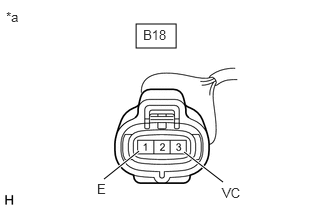
1.417,0.25 1.833,0.5 0.417,0.25 1.448,1.573 1.083,1.865 true 1.917,1.583 2.323,1.896 true 0.063,0.094 0.375,0.25 0.313,0.156 10 false *a 2.313,1.927 2.625,2.125 0.313,0.198 10 false VC 1.01,1.885 1.323,2.083 0.313,0.198 10 false E 1.49,0.281 1.948,0.521 0.458,0.24 10 false B18
*a Front view of wire harness connector
(to Air Conditioning Pressure Sensor)


Disconnect the air conditioning pressure sensor connector.


b.

Measure the voltage according to the value(s) in the table below.

Standard Voltage:
Tester Connection Switch Condition Specified Condition
B18-3 (VC) - B18-1 (E) Ignition switch ON 4.75 to 5.25 V


Result:
Proceed to
OK
NG


OK

2.INSPECT AIR CONDITIONING PRESSURE SENSOR (SENSOR SIGNAL CIRCUIT)

NG

3.CHECK HARNESS AND CONNECTOR (ECM - AIR CONDITIONING PRESSURE SENSOR)
2.INSPECT AIR CONDITIONING PRESSURE SENSOR (SENSOR SIGNAL CIRCUIT)
a.
A325102C01
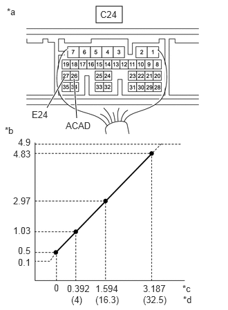
1.448,0.094 1.844,0.344 0.396,0.25 1.156,1.781 1.115,1.188 true 0.708,1.625 0.969,1.177 true 0.479,1.646 0.938,1.844 0.458,0.198 10 false E24 0.99,1.813 1.448,2.01 0.458,0.198 10 false ACAD 0.104,0.094 0.563,0.292 0.458,0.198 10 false *a 1.51,0.135 1.969,0.333 0.458,0.198 10 false C24 0.073,1.885 0.531,2.083 0.458,0.198 10 false *b 0.271,2.063 0.563,2.24 0.292,0.177 10 false 4.9 0.198,2.24 0.604,2.469 0.406,0.229 10 false 4.83 0.198,2.948 0.604,3.177 0.406,0.229 10 false 2.97 0.198,3.396 0.604,3.625 0.406,0.229 10 false 1.03 0.271,3.698 0.677,3.927 0.406,0.229 10 false 0.5 0.271,3.875 0.677,4.104 0.406,0.229 10 false 0.1 0.813,4.26 1.219,4.49 0.406,0.229 10 false 0 2.156,4.271 2.563,4.5 0.406,0.229 10 false 3.187 1.438,4.271 1.844,4.5 0.406,0.229 10 false 1.594 1.01,4.271 1.417,4.5 0.406,0.229 10 false 0.392 2.75,4.271 2.969,4.458 0.219,0.188 10 false *c 2.76,4.438 2.979,4.625 0.219,0.188 10 false *d 2.156,4.438 2.531,4.635 0.375,0.198 10 false (32.5) 1.438,4.438 1.813,4.635 0.375,0.198 10 false (16.3) 1.073,4.438 1.448,4.635 0.375,0.198 10 false (4)
*a Component with harness connected
(ECM)
*b Output Voltage (V)
*c Refrigerant Pressure (MPa)
*d Refrigerant Pressure (kgf/cm2)


Reconnect the air conditioning pressure sensor connector.


b.

Measure the voltage according to the value(s) in the table below.

Specified Conditions:
Tester Connection Specified Condition
C24-26 (ACAD) - C24-27 (E24) The transition of the pressure is as shown in the illustration due to the refrigerant pressure*.


*: Sensor power supply voltage is 5 V.


Result:
Proceed to
OK
NG


OK

NG

4.CHECK HARNESS AND CONNECTOR (ECM - AIR CONDITIONING PRESSURE SENSOR)
3.CHECK HARNESS AND CONNECTOR (ECM - AIR CONDITIONING PRESSURE SENSOR)
a.

Disconnect the ECM connector.


b.

Disconnect the air conditioning pressure sensor connector.


c.

Measure the resistance according to the value(s) in the table below.

Standard Resistance (Check for Open):
Tester Connection Condition Specified Condition
C24-21 (VCO) - B18-3 (VC) Always Below 1 Ω
C24-27 (E24) - B18-1 (E) Always Below 1 Ω


Standard Resistance (Check for Short):
Tester Connection Condition Specified Condition
C24-21 (VCO) or B18-3 (VC) - Body ground Always 10 kΩ or higher
C24-27 (E24) or B18-1 (E) - Body ground Always 10 kΩ or higher


Result:
Proceed to
OK
NG


OK

NG

REPAIR OR REPLACE HARNESS OR CONNECTOR

4.CHECK HARNESS AND CONNECTOR (ECM - AIR CONDITIONING PRESSURE SENSOR)
a.

Disconnect the ECM connector.


b.

Disconnect the air conditioning pressure sensor connector.


c.

Measure the resistance according to the value(s) in the table below.

Standard Resistance (Check for Open):
Tester Connection Condition Specified Condition
C24-26 (ACAD) - B18-2 (VOUT) Always Below 1 Ω


Standard Resistance (Check for Short):
Tester Connection Condition Specified Condition
C24-26 (ACAD) or B18-2 (VOUT) - Body ground Always 10 kΩ or higher


Result:
Proceed to
OK
NG


OK

NG

REPAIR OR REPLACE HARNESS OR CONNECTOR