STEERING COLUMN STEERING COLUMN ASSEMBLY REMOVAL
CAUTION / NOTICE / HINT
- HINT:
- ·
The procedure described below is for the RHD vehicles.
·Use the same procedure for both the RHD and LHD vehicles.
PROCEDURE

 45100
1.REMOVE STEERING WHEEL SUB-ASSEMBLY
45287
2.REMOVE LOWER STEERING COLUMN COVER
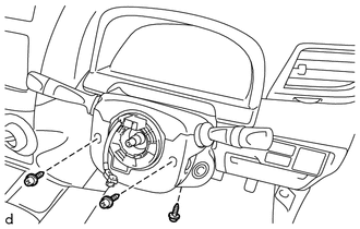
Remove the 3 screws.
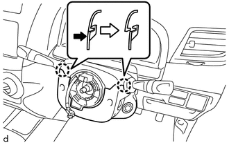
Push the right and left sides of the lower steering column cover to disengage the 2 claws and remove the lower steering column cover.
45286B
3.REMOVE UPPER STEERING COLUMN COVER
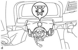
Disengage the claw and remove the upper steering column cover.
4.REMOVE COMBINATION SWITCH ASSEMBLY WITH SPIRAL CABLE
- NOTICE:
- ·
Do not replace the spiral cable with sensor sub-assembly with the battery connected and the ignition switch ON.
·Do not rotate the spiral cable with sensor sub-assembly without the steering wheel assembly with the battery connected and the ignition switch ON.
·Ensure that the steering wheel assembly is installed and aligned straight when inspecting the steering sensor.
Disconnect all the connectors from the combination switch assembly with spiral cable.
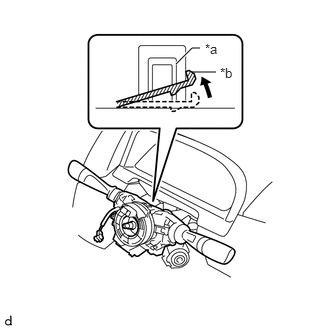
| *a | Clamp |
| *b | Claw |
Use pliers to hold the clamp and raise the claw with a screwdriver. Remove the combination switch assembly with spiral cable from the steering column assembly.
89650
5.REMOVE POWER STEERING ECU ASSEMBLY
89782
6.REMOVE TRANSPONDER KEY COIL (w/ Engine Immobiliser System)
45250
7.REMOVE STEERING COLUMN ASSEMBLY
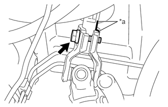
| *a | Matchmark |
Put matchmarks on the steering intermediate shaft assembly and steering column assembly.
Remove the bolt on the upper side of the steering intermediate shaft assembly.
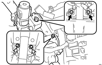

|
Bolt |

|
Nut |
Remove the 2 bolts and 2 nuts.
Pull out the steering column assembly avoiding the EPS motor being caught.
- NOTICE:
- ·
Be careful not to damage the brake booster assembly by hitting with the steering main shaft.
·Be careful not to damage the steering column hole shield.
45254
8.REMOVE STEERING COLUMN HOLE SHIELD
Remove the steering column hole shield from the floor panel.