2NR-VE ENGINE CONTROL THROTTLE BODY INSTALLATION
PROCEDURE

 22271A
1.INSTALL THROTTLE BODY GASKET
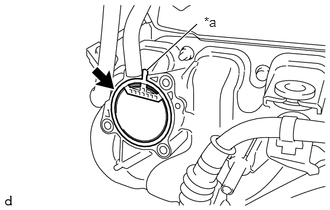
| *a | Protrusion |
Install a new throttle body gasket onto the intake manifold.
- HINT:
-
Orient the protrusion of the throttle body gasket as shown in the illustration.
22030
2.INSTALL THROTTLE BODY WITH MOTOR ASSEMBLY
Install the throttle body with motor assembly with the 3 bolts.
- Torque:
- 10 N*m (102 kgf*cm, 7 ft.*lbf)
- NOTICE:
-
If a component has been dropped or subjected to a strong impact, replace it.
Connect the throttle body with motor assembly connector.
16264
3.CONNECT NO. 2 WATER BY-PASS HOSE (w/ Heater)
Connect the No. 2 water by-pass hose with the clip.
16261
4.CONNECT NO. 1 WATER BY-PASS HOSE (w/ Heater)
Connect the No. 1 water by-pass hose with the clip.
17881
5.INSTALL NO. 1 AIR CLEANER HOSE
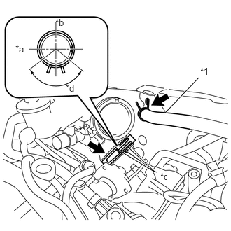
| *1 | No. 2 Ventilation Hose |
| *a | Front Side |
| *b | RH Side |
| *c | Projection |
| *d | 135° |
Install the No. 1 air cleaner hose to the throttle with motor body assembly with the hose clamp as shown in the illustration.
- HINT:
- ·
Fit the projection on the throttle body with motor assembly into the space between the projections on the No. 1 air cleaner hose.
- ·
Install the hose clamp so that it is positioned as shown in the illustration.
Connect the No. 2 ventilation hose with the clip.
17700
6.INSTALL AIR CLEANER ASSEMBLY
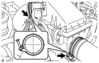
| *1 | No. 1 Air Cleaner Hose |
| *2 | No. 2 Air Cleaner Hose |
| *a | Stopper |
Install the air cleaner assembly with the 2 bolts.
- Torque:
- 7.8 N*m (80 kgf*cm, 69 in.*lbf)
Connect the No. 1 air cleaner hose with the hose clamp.
- Torque:
- 3.0 N*m (31 kgf*cm, 27 in.*lbf)
- NOTICE:
-
Install the hose clamp so that the clamp makes contact with the stopper.
Connect the No. 2 air cleaner hose with the hose clamp.
- Torque:
- 3.0 N*m (31 kgf*cm, 27 in.*lbf)
- NOTICE:
-
Install the hose clamp so that the clamp makes contact with the stopper.
Connect the harness clamp and connector to the intake air flow meter assembly.
Connect the harness clamp to the air cleaner cap sub-assembly.
Engage the 2 guides and connect the No. 1 charcoal canister outlet hose to the air cleaner cap sub-assembly (for LHD).
Engage the guide and connect the No. 2 ventilation hose to the air cleaner cap sub-assembly.
Connect the No. 2 fuel vapor feed hose, No. 1 charcoal canister hose and connector to the No. 1 vacuum switching valve assembly.
7.ADD ENGINE COOLANT (w/ Heater)
8.INSPECT FOR COOLANT LEAK (w/ Heater)
51473A
9.INSTALL ENGINE SIDE COVER SUB-ASSEMBLY RH (w/ Heater)