1NR-VE ENGINE MECHANICAL ENGINE UNIT INSTALLATION
PROCEDURE

 16281
1.CONNECT NO. 4 WATER BY-PASS HOSE
Connect the No. 4 water by-pass hose with the clip.
16620
2.INSTALL V-RIBBED BELT TENSIONER ASSEMBLY
Install the V-ribbed belt tensioner assembly with the 2 bolts.
- Torque:
- 21 N*m (214 kgf*cm, 15 ft.*lbf)
16603
3.INSTALL NO. 1 IDLER PULLEY SUB-ASSEMBLY (w/ Air Conditioning System)
Install the idler pulley spacer, No. 1 idler pulley sub-assembly and idler pulley plate with the bolt.
- Torque:
- 44 N*m (449 kgf*cm, 32 ft.*lbf)
88431
4.INSTALL NO. 1 COMPRESSOR MOUNTING BRACKET (w/ Air Conditioning System)
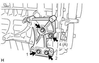
Temporarily install the No. 1 compressor mounting bracket with the bolt (A).
Temporarily tighten the 3 bolts.
Fully tighten the 4 bolts in the order shown in the illustration.
- Torque:
- 22.5 N*m (229 kgf*cm, 17 ft.*lbf)
23250
5.INSTALL FUEL INJECTOR ASSEMBLY
23291
6.INSTALL INJECTOR VIBRATION INSULATOR
23807V
7.INSTALL NO. 1 DELIVERY PIPE SPACER
23814B
8.INSTALL FUEL DELIVERY PIPE
23901
9.CONNECT FUEL TUBE SUB-ASSEMBLY
23842A
10.INSTALL EFI FUEL PIPE CLAMP
11.INSTALL HARNESS BRACKET
Install the harness bracket with the bolt.
- Torque:
- 7.0 N*m (71 kgf*cm, 62 in.*lbf)
16282
12.INSTALL NO. 5 WATER BY-PASS HOSE
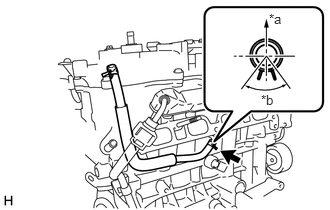
| *a | Upper Side |
| *b | 90° |
Install the No. 5 water by-pass hose to the cylinder block sub-assembly with the clip as shown in the illustration.
- HINT:
-
Install the clip so that it is positioned as shown in the illustration.
16267D
13.INSTALL 3-WAY
Install the 3-way with the clip.
16267
14.CONNECT NO. 3 WATER BY-PASS HOSE
Connect the No. 3 water by-pass hose to the 3 way with the clip.
16261
15.INSTALL WATER BY-PASS HOSE (w/o Heater)
Install the water by-pass hose with the 2 clips.
16261
16.CONNECT WATER BY-PASS HOSE (w/ Heater)
Connect water by-pass hose with the clip.
16264
17.CONNECT NO. 2 WATER BY-PASS HOSE (w/ Heater)
Connect No. 2 water by-pass hose with the clip.
12262
18.INSTALL NO. 2 VENTILATION HOSE
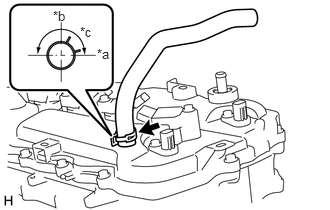
| *a | Front Side |
| *b | LH Side |
| *c | 90° |
Connect the No. 2 ventilation hose with the clip as shown in the illustration.
- HINT:
-
Install the clip so that it is positioned as shown in the illustration.
77775
19.INSTALL CHARCOAL CANISTER OUTLET GUIDE (for RHD)
Install the charcoal canister outlet guide.