2NR-VE FUEL FUEL PUMP INSTALLATION
PROCEDURE

 77020A
1.INSTALL FUEL SUCTION TUBE WITH PUMP AND GAUGE ASSEMBLY
Install a new fuel pump bracket gasket onto the fuel suction tube with pump and gauge assembly.
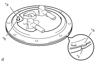
| *a | Protrusion |
| *b | Hole |
| *c | Concave |
Align the protrusion of the fuel suction tube with pump and gauge assembly with the hole in the No. 1 fuel pump bracket as illustrated.
Align the protrusion of the No. 1 fuel pump bracket with the concave of the fuel tank assembly.
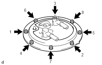
Tighten the 8 screws in the sequence shown in the illustration.
- Torque:
- 3.8 N*m (39 kgf*cm, 34 in.*lbf)
Connect the fuel pump connector.
77204A
2.INSTALL FUEL TANK RETURN TUBE
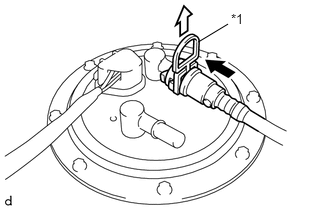
| *1 | Checker |

|
Push |

|
Pull out |
Align a new fuel tank return tube with the fuel pump tube, then push in the fuel return tube until the retainer makes a click sound. Then, pull out the checker.
- NOTICE:
- ·
Check that there are no scratches or foreign matter around the connected parts of the fuel pump tube and fuel tank return tube before performing this work.
·After connecting the fuel tank return tube, check that the fuel pump tube and fuel tank return tube are securely connected by pulling them.
- HINT:
-
If connecting the tubes is too tight, apply a light coat of appropriate lubricant or gasoline to the tip of the fuel pump tube.
Attach the fuel tank return tube to the No. 1 fuel tube clamp.
Attach the fuel tank return tube to the No. 2 fuel tube clamp.
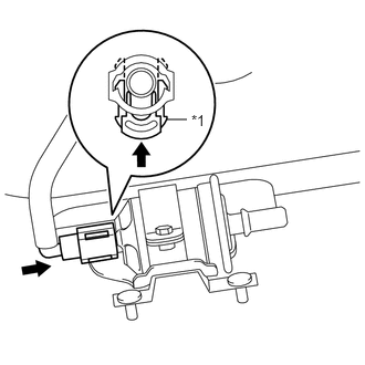
| *1 | Retainer |
|
|
Push |
Insert the fuel tank return tube until it comes into contact with the fuel filter tube, then push in the retainer until it makes a click sound.
- NOTICE:
- ·
Check that there are no scratches or foreign matter around the connected parts of the fuel filter tube and fuel tank return tube before this work.
·After connecting the fuel tank return tube, check that the fuel filter tube and fuel tank return tube are securely connected by pulling them.
- HINT:
-
If connecting the tubes is too tight, apply a light coat of appropriate lubricant or gasoline to the tip of the fuel filter tube.
Attach the fuel tank return tube to the No. 1 fuel tube clamp.
77203A
3.INSTALL FUEL SUCTION TUBE SUB-ASSEMBLY
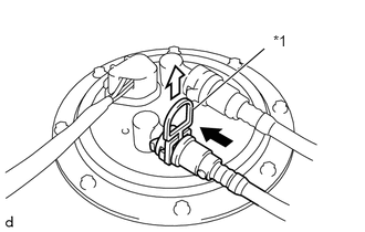
| *1 | Checker |
|
|
Push |
|
|
Pull out |
Align a new fuel suction tube sub-assembly with the fuel pump tube, then push in the fuel suction tube until the retainer makes a click sound. Then, pull out the checker.
- NOTICE:
- ·
Check that there are no scratches or foreign matter around the connected parts of the fuel pump tube and fuel suction tube sub-assembly before performing this work.
·After connecting the fuel suction tube sub-assembly, check that the fuel pump tube and fuel suction tube sub-assembly are securely connected by pulling them.
- HINT:
-
If connecting the tubes is too tight, apply a light coat of appropriate lubricant or gasoline to the tip of the fuel pump tube.
Attach the fuel suction tube sub-assembly to the No. 1 fuel tube clamp.
Attach the fuel suction tube sub-assembly to the No. 2 fuel tube clamp.
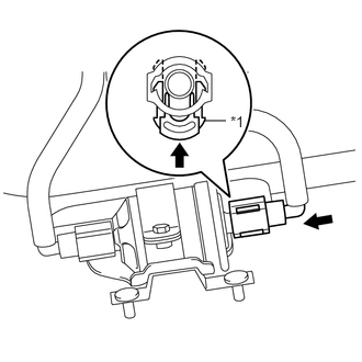
| *1 | Retainer |
|
|
Push |
Insert the fuel suction tube sub-assembly until it comes into contact with the fuel filter tube, then push in the retainer until it makes a click sound.
- NOTICE:
- ·
Check that there are no scratches or foreign matter around the connected parts of the fuel filter tube and fuel suction tube sub-assembly before this work.
·After connecting the fuel suction tube sub-assembly, check that the fuel filter tube and fuel suction tube sub-assembly are securely connected by pulling them.
- HINT:
-
If connecting the tubes is too tight, apply a light coat of appropriate lubricant or gasoline to the tip of the fuel filter tube.
Attach the fuel suction tube sub-assembly to the No. 1 fuel tube clamp.
77100
4.INSTALL FUEL TANK ASSEMBLY