1NR-VE INTAKE / EXHAUST INTAKE MANIFOLD INSTALLATION
PROCEDURE

 17177
1.INSTALL NO. 1 INTAKE MANIFOLD TO HEAD GASKET
Install a new No. 1 intake manifold to head gasket to the intake manifold.
12261
2.CONNECT VENTILATION HOSE
Connect the ventilation hose to the intake manifold.
17111
3.INSTALL INTAKE MANIFOLD

|
Bolt |

|
Nut |
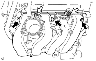
Temporarily install the intake manifold, and then uniformly tighten the 3 bolts and 2 nuts in several steps in the sequence shown in the illustration.
- Torque:
- 28 N*m (286 kgf*cm, 21 ft.*lbf)
Install the wire harness bracket with the bolt.
- Torque:
- 7.0 N*m (71 kgf*cm, 62 in.*lbf)
Connect the 4 harness clamps and engine wire harness to the intake manifold.
4.INSTALL GROMMET
Install the grommet to the intake manifold.
44730A
5.CONNECT NO. 1 VACUUM HOSE
| *a | Upper Side |
| *b | Front Side |
| *c | 180° |
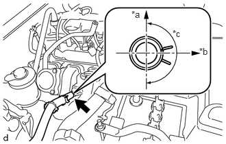
Connect the No. 1 vacuum hose to the intake manifold with the clip as shown in the illustration.
- HINT:
-
Install the clip so that it is positioned as shown in the illustration.
23827A
6.CONNECT NO. 2 FUEL VAPOR FEED HOSE
Connect the No. 2 fuel vapor feed hose.
12261
7.INSTALL VENTILATION HOSE
| *a | Front Side |
| *b | RH Side |
| *c | 180° |
| *d | Paint Mark (Yellow) |
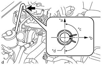
Install the ventilation hose with the clip to the cylinder head cover sub-assembly as shown in the illustration.
- HINT:
-
Install the clip so that it is positioned as shown in the illustration.
11452
8.INSTALL OIL LEVEL DIPSTICK GUIDE
Install a new O-ring to the oil level dipstick guide.
Install the oil level dipstick guide with the bolt.
- Torque:
- 10 N*m (102 kgf*cm, 7 ft.*lbf)
Connect the 2 harness clamps.
22030
9.INSTALL THROTTLE BODY WITH MOTOR ASSEMBLY
17750A
10.INSTALL AIR CLEANER INLET ASSEMBLY