POWER ASSIST SYSTEMS POWER STEERING SYSTEM C1511/11 Torque Sensor1 C1512/12 Torque Sensor2 C1513/13 Torque Sensor Deviation Excessive C1514/14 Torque Sensor Power Supply Abnormal
DESCRIPTION
The power steering ECU calculates assisting power based on steering torque signals from the torque sensor. If these DTCs are stored in the power steering ECU assembly, the ECU stops steering power assist as a fail-safe function.
| DTC No. | Detection Item | DTC Detection Condition | Trouble Area | Warning Indicate | Return-to-normal Condition | Note |
|---|---|---|---|---|---|---|
| C1511/11 | Torque Sensor1 | Torque sensor (TRQ1) signal error or stop | ·
Steering column assembly (torque sensor) ·
Power steering ECU |
Comes on (Red) | Ignition switch ON again | Buzzer :
Sounds in termittently |
| C1512/12 | Torque Sensor2 | Torque sensor (TRQ2) signal error or stop | ·
Steering column assembly (torque sensor) ·
Power steering ECU |
Comes on (Red) | Ignition switch ON again | Buzzer :
Sounds in termittently |
| C1513/13 | Torque Sensor Deviation Excessive | The total output voltage of torque sensor (TRQ1) and torque sensor (TRQ2) is out of the specified value*. | ·
Steering column assembly (torque sensor) ·
Power steering ECU |
Comes on (Red) | Ignition switch ON again | Buzzer :
Sounds in termittently |
| C1514/14 | Torque Sensor Power Supply Abnormal | Torque sensor power source voltage error | ·
Steering column assembly (torque sensor) ·
Power steering ECU |
Comes on (Red) | Ignition switch ON again | Buzzer :
Sounds in termittently |
*: The total output voltage of torque sensor (TRQ1) and torque sensor (TRQ2) is 4.8 V or lower, or 5.2 V or higher.
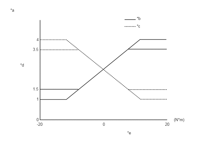
| *a | Output voltage characteristics with power supply voltage 5 V | *b | TORQ1 |
| *c | TORQ2 | *d | Output voltage |
| *e | Input torque | - | - |
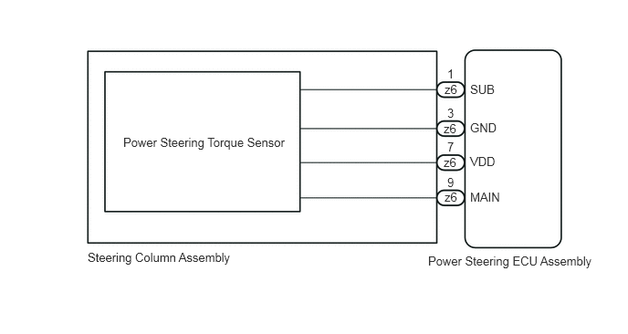
WIRING DIAGRAM
PROCEDURE
Check the connection condition of the z6 torque sensor connector.
- OK:
Torque sensor connector is securely connected to the power steering ECU assembly.
- Result:
Proceed to OK NG
OK
NG
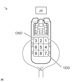
| *a | Component with harness connected
(Power Steering ECU Assembly) |
Turn the ignition switch to ON.
Measure the voltage according to the value(s) in the table below.
- Standard Voltage:
Tester Connection Switch Condition Specified Condition z6-7 (VDD) - z6-3 (GND) Ignition switch ON 4.5 to 5.5 V
- Result:
Proceed to OK NG
OK
NG
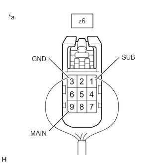
| *a | Component with harness connected
(Power Steering ECU Assembly) |
Turn the ignition switch to ON.
Measure the voltage according to the value(s) in the table below.
- Standard Voltage:
Tester Connection Switch Condition
(Steering Position)Specified Condition z6-9 (MAIN) - z6-3 (GND) Engine running, steering wheel not turned (without load) 2.2 to 2.8 V Engine running, steering wheel turned to right with vehicle stopped 2.2 to 4.85 V Engine running, steering wheel turned to left with vehicle stopped 0.15 to 2.8 V z6-1 (SUB) - z6-3 (GND) Engine running, steering wheel not turned (without load) 2.2 to 2.8 V Engine running, steering wheel turned to right with vehicle stopped 0.15 to 2.8 V Engine running, steering wheel turned to left with vehicle stopped 2.2 to 4.85 V
Check the total voltage of Torque Sensor 1 Output and Torque Sensor 2 Output in the Data List.
- Chassis > EPS > Data List
-
Tester Display Normal Condition Diagnostic Note Output of torque sensor 1 4.8 to 5.2 V ·Steering wheel not turned (without load)
·Steering wheel turned to right with vehicle stopped
·Steering wheel turned to left with vehicle stopped
Output of torque sensor 2 4.8 to 5.2 V ·Steering wheel not turned (without load)
·Steering wheel turned to right with vehicle stopped
·Steering wheel turned to left with vehicle stopped
- Chassis > EPS > Data List
-
Tester Display Output of torque sensor 1 Output of torque sensor 2 - 50003 581 10,11
- OK:
A value within the range listed in the normal condition column is displayed on the GTS or Techstream during each steering operation.
- Result:
Proceed to OK NG
OK
NG