Home › Steering › POWER ASSIST SYSTEMS › POWER STEERING SYSTEM › from 2015.08
RM19Y0E _55 Steering _002997 POWER ASSIST SYSTEMS _0015160 POWER STEERING SYSTEM J

POWER ASSIST SYSTEMS  POWER STEERING SYSTEM  EPS Warning Light Circuit  


DESCRIPTION

If the power steering ECU detects a malfunction, the P/S warning light comes on. At this time, the power steering ECU stores the appropriate DTC.

WIRING DIAGRAM
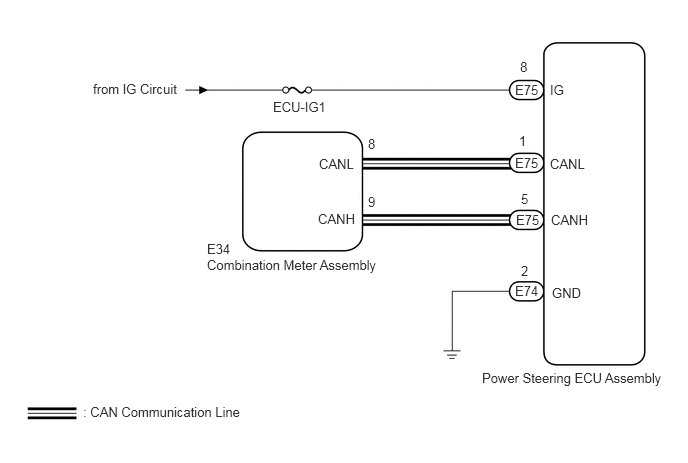
C332596E02
5.021,3.854 7.031,4.104 2.01,0.25 10 false Power Steering ECU Assembly 2.156,2.677 4.167,2.927 2.01,0.25 10 false Combination Meter Assembly 2.844,1.031 3.51,1.26 0.667,0.229 10 false ECU-IG1 5.729,1.625 6.396,1.854 0.667,0.229 10 false CANL 3.313,2.198 3.76,2.396 0.448,0.198 10 false CANH 3.323,1.625 3.771,1.833 0.448,0.208 10 false CANL 5.74,2.208 6.406,2.438 0.667,0.229 10 false CANH 5.406,1.385 5.656,1.615 0.25,0.229 10 false 1 5.75,2.969 6.417,3.198 0.667,0.229 10 false GND 5.365,0.854 5.667,1.063 0.302,0.208 10 false E75 5.375,2.208 5.677,2.417 0.302,0.208 10 false E75 5.365,1.615 5.667,1.823 0.302,0.208 10 false E75 5.365,2.948 5.667,3.156 0.302,0.208 10 false E74 5.427,1.99 5.677,2.219 0.25,0.229 10 false 5 5.427,2.74 5.677,2.969 0.25,0.229 10 false 2 5.417,0.615 5.667,0.844 0.25,0.229 10 false 8 0.865,4.208 2.875,4.458 2.01,0.25 10 false : CAN Communication Line 5.729,0.854 6.396,1.083 0.667,0.229 10 false IG 0.969,0.844 1.99,1.083 1.021,0.24 10 false from IG Circuit 2.156,2.51 2.458,2.719 0.302,0.208 10 false E34 3.833,2.021 4.083,2.25 0.25,0.229 10 false 9 3.833,1.417 4.083,1.646 0.25,0.229 10 false 8

CAUTION / NOTICE / HINT

HINT:

Inspect the fuses for circuits related to this system before performing the following inspection procedure.


PROCEDURE

1.CHECK HARNESS AND CONNECTOR
a.

Turn the ignition switch to ON.


b.

Check the indication condition of the EPS warning light by wiggling the power steering ECU assembly connector and wire harness up and down, and right and left.

OK:

EPS warning light indication condition does not change.


Result:
Proceed to
OK
NG


OK

2.CHECK CAN COMMUNICATION SYSTEM

NG

REPAIR OR REPLACE HARNESS OR CONNECTOR

2.CHECK CAN COMMUNICATION SYSTEM
a.

Check if a CAN communication system DTC is output.

Click herePower Source / Network>NETWORKING>CAN COMMUNICATION SYSTEM>DIAGNOSIS SYSTEM

Result:
Result Proceed to
DTC is not output A
DTC is output B


A

3.CHECK HARNESS AND CONNECTOR (POWER SUPPLY)

B

GO TO CAN COMMUNICATION SYSTEM (HOW TO PROCEED WITH TROUBLESHOOTING)

3.CHECK HARNESS AND CONNECTOR (POWER SUPPLY)
a.
C331488C03
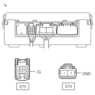
2.26,3 2.698,3.25 0.438,0.25 0.604,3 1.042,3.25 0.438,0.25 2.667,2.635 2.927,2.635 true 1.01,2.583 1.271,2.583 true 0.115,0.104 0.427,0.302 0.313,0.198 10 false *a 2.365,3.042 2.677,3.24 0.313,0.198 10 false E74 2.979,2.583 3.354,2.792 0.375,0.208 10 false GND 0.708,3.052 1.021,3.25 0.313,0.198 10 false E75 1.333,2.521 1.708,2.729 0.375,0.208 10 false IG
*a Front view of wire harness connector
(to Power Steering ECU Assembly)


Disconnect the E74 and E75 power steering ECU assembly connectors.


b.

Measure the voltage and resistance according to the value(s) in the table below.

Standard Voltage:
Tester Connection Condition Specified Condition
E75-8 (IG) - Body ground Ignition switch ON 11 to 14 V


Standard Resistance:
Tester Connection Condition Specified Condition
E74-2 (GND) - Body ground Always Below 1 Ω


Result:
Proceed to
OK
NG


OK

4.REPLACE POWER STEERING ECU ASSEMBLY

NG

REPAIR OR REPLACE HARNESS OR CONNECTOR

4.REPLACE POWER STEERING ECU ASSEMBLY
a.

Replace the power steering ECU assembly.

Click hereSteering>POWER ASSIST SYSTEMS>POWER STEERING ECU>REMOVAL

Result:
Proceed to
NEXT


NEXT

5.CHECK WARNING LIGHT
a.

Turn the ignition switch to ON.


b.

Check that the EPS warning light illuminates.

Result:
Result Proceed to
Lights for several seconds and then goes off A
Remains on B


A

END

B

REPLACE COMBINATION METER ASSEMBLY