METER / GAUGE / DISPLAY METER / GAUGE SYSTEM Speed Signal Circuit
DESCRIPTION
The combination meter assembly receives the vehicle speed signal from this circuit. The wheel speed sensors produce an output that varies according to the vehicle speed. The wheel speed sensor output is received by the skid control ECU (brake actuator assembly) which uses this information to create the vehicle speed signal*. The combination meter assembly receives the vehicle speed signal from the skid control ECU (brake actuator assembly) via CAN communication to control the speedometer. Additionally, the combination meter assembly relays this signal to other systems. When a voltage of 12 V or 5 V from each control ECU that requires a vehicle speed signal is applied to the SPDO terminal, the combination meter assembly converts this voltage into required waveform based on the vehicle speed signal received via CAN communication, and then outputs a vehicle speed signal to other systems.
*: This vehicle speed signal is created by the skid control ECU (brake actuator assembly). There is no actual component that is referred to as the vehicle speed sensor. In addition, for some systems, vehicle speed information may be received via CAN communication.
- HINT:
-
This circuit is used for the systems connected to terminal SPDO. This signal is not used for combination meter assembly operation. Combination meter assembly components such as the speedometer operate using data received via CAN communication.
WIRING DIAGRAM
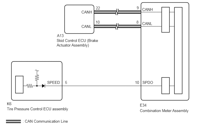
PROCEDURE
Connect the GTS or Techstream to the DLC3.
Turn the ignition switch to ON.
Turn the GTS or Techstream on.
Enter the following menus: Body Electrical / Meter / Data List.
| Tester Display | Measurement Item | Range | Normal Condition | Diagnostic Note |
|---|---|---|---|---|
| Vehicle Speed | Vehicle speed | Min.: 0 km/h (0 mph), Max.: 255 km/h (158 mph) | Almost the same as actual vehicle speed | - |
- HINT:
-
Using a speedometer tester, check the actual vehicle speed and the vehicle speed displayed on the GTS or Techstream.
- OK:
Vehicle speed displayed on the GTS is almost the same as the actual vehicle speed measured using a speedometer tester.
- Result:
Proceed to OK NG
OK
NG
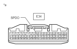
Disconnect the E34 combination meter assembly connector.
Measure the voltage according to the value(s) in the table below.
- Standard Voltage:
Tester Connection Switch Condition Specified Condition E34-10 (SPDO) - Body ground Ignition switch ON 4.5 to 14 V
- HINT:
-
If any of the ECUs specified in the wiring diagram supplies power to the combination meter assembly, the combination meter assembly will output a waveform.
- Result:
Proceed to OK NG
OK
NG
Disconnect the E34 combination meter assembly connector.
Disconnect the K6 tire pressure control ECU assembly connector.
Measure the resistance according to the value(s) in the table below.
- Standard Resistance (Check for Open):
Tester Connection Condition Specified Condition E34-10 (SPDO) - K6-5 (SPEED) Always Below 1 Ω
- Standard Resistance (Check for Short):
Tester Connection Condition Specified Condition E9-10 (SPDO) or K6-5 (SPEED) - Body ground Always 10 kΩ or higher
- Result:
Proceed to OK NG
OK
NG