AUDIO / VIDEO STEREO COMPONENT AMPLIFIER REMOVAL
CAUTION / NOTICE / HINT
The necessary procedures (adjustment, calibration, initialization, or registration) that must be performed after parts are removed and installed, or replaced during the stereo component amplifier assembly removal/installation are shown below.
| Replaced Part or Performed Procedure | Necessary Procedure | Effect/Inoperative Function when Necessary Procedure not Performed | Link |
|---|---|---|---|
| Disconnect cable from negative auxiliary battery terminal | Memorize steering angle neutral point | Lane departure alert system (w/ Steering Control) | ( ) |
| Simple intelligent parking assist system*1 | |||
| Toyota parking assist-sensor system*1 | |||
| Pre-collision system | |||
| Initialize back door lock | Power door lock control system | ()
|
*1: When performing learning using the GTS.
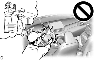
- CAUTION:
-
-
Some of these service operations affect the SRS airbag system. Read the precautionary notices concerning the SRS airbag system before servicing.
-
Click hereVehicle Interior>SUPPLEMENTAL RESTRAINT SYSTEMS>AIRBAG SYSTEM>PRECAUTION
- HINT:
- ·
Use the same procedure for RHD and LHD vehicles.
·The procedure listed below is for LHD vehicles.
PROCEDURE

 1.REMOVE FRONT SEAT ASSEMBLY LH
86183D
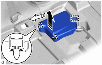
2.REMOVE AUDIO AMPLIFIER COVER

|
Remove in this Direction (1) |

|
Remove in this Direction (2) |
Pull the audio amplifier cover in the direction indicated by the arrow (1) shown in the illustration to disengage the clips.
Pull the audio amplifier cover in the direction indicated by the arrow (2) shown in the illustration to disengage the guide to remove the audio amplifier cover.
86280
3.REMOVE STEREO COMPONENT AMPLIFIER ASSEMBLY WITH BRACKET
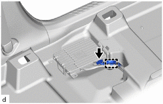
Disengage the clamp.
Disconnect the connector.
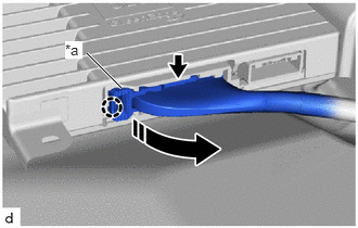
| *a | Lock Lever |
|
|
Remove in this Direction |
Disengage the claw and pull the lock lever to disconnect the connector as shown in the illustration.
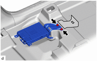
Turn back the part of the front floor carpet assembly.
Remove the 2 bolts and remove the stereo component amplifier assembly with bracket.
86286
4.REMOVE NO. 2 AMPLIFIER BRACKET
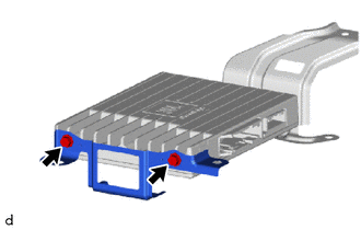
Remove the 2 screws and No. 2 amplifier bracket from the stereo component amplifier assembly.
86285
5.REMOVE NO. 1 AMPLIFIER BRACKET
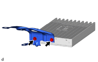
Remove the 2 screws and No. 1 amplifier bracket from the stereo component amplifier assembly.