PARK ASSIST / MONITORING CLEARANCE WARNING ECU REMOVAL
CAUTION / NOTICE / HINT
The necessary procedures (adjustment, calibration, initialization, or registration) that must be performed after parts are removed and installed, or replaced during the clearance warning ECU assembly removal/installation are shown below.
| Replaced Part or Performed Procedure | Necessary Procedure | Effect/Inoperative Function when Necessary Procedure not Performed | Link |
|---|---|---|---|
| Disconnect cable from negative battery terminal | Memorize steering angle neutral point | Lane departure alert system (w/ Steering Control) | ( ) |
| Simple intelligent parking assist system*1 | |||
| Toyota parking assist-sensor system (w/ Simple Intelligent Parking Assist System)*1 | |||
| Pre-collision System | |||
| Initialize back door lock | Power door lock control system | ()
|
|
| Replacement of clearance warning ECU assembly | ·
Steering angle neutral point ·
Registration of bumper type |
·
Simple Intelligent Parking Assist System ·
Toyota parking assist-sensor system (w/ Simple Intelligent Parking Assist System) |
()
|
| Registration of bumper type | Toyota parking assist-sensor system (w/o Simple Intelligent Parking Assist System) | ()
|
*1: When performing learning using the GTS.
- CAUTION:
-
-
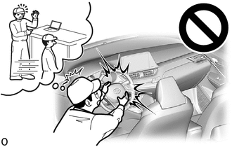
Some of these service operations affect the SRS airbag system. Read the precautionary notices concerning the SRS airbag system before servicing.
-
Click hereVehicle Interior>SUPPLEMENTAL RESTRAINT SYSTEMS>AIRBAG SYSTEM>PRECAUTION
- HINT:
- ·
Use the same procedure for LHD and RHD vehicles.
·The procedure listed below is for the LHD vehicles.
PROCEDURE

 55470
1.REMOVE INSTRUMENT CLUSTER FINISH PANEL GARNISH ASSEMBLY
55434B
2.REMOVE INSTRUMENT PANEL LOWER CENTER FINISH PANEL
55440D
3.REMOVE INSTRUMENT PANEL BOX ASSEMBLY
55406B
4.REMOVE INSTRUMENT CLUSTER FINISH LOWER CENTER PANEL SUB-ASSEMBLY
86841
5.REMOVE NAVIGATION ECU WITH BRACKET (w/ Navigation System)
82660B
6.SEPARATE RELAY BLOCK ASSEMBLY
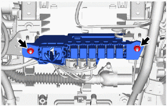
Remove the 2 nuts and separate the relay block assembly.
89343C
7.REMOVE NO. 1 CLEARANCE WARNING BUZZER
89340A
8.REMOVE CLEARANCE WARNING ECU ASSEMBLY
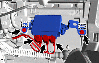
Disconnect the 3 connectors.
Remove the 2 screws.
Disengage the guides to remove the clearance warning ECU assembly.