METER / GAUGE / DISPLAY METER / GAUGE SYSTEM Hybrid System Indicator Malfunction
DESCRIPTION
A hybrid system indicator has been included on this vehicle. In this circuit, the combination meter assembly receives the eco-zone indicator level signal from the hybrid vehicle control ECU via CAN communication. The combination meter assembly controls the operation of the hybrid system indicator according to the eco-zone indicator level signal received from the hybrid vehicle control ECU via CAN communication.
WIRING DIAGRAM
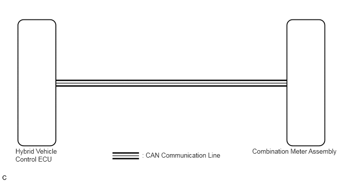
CAUTION / NOTICE / HINT
- NOTICE:
- ·
Before replacing the hybrid vehicle control ECU, refer to Service Bulletin.
·When replacing the combination meter assembly, always replace it with a new one. If a combination meter assembly which was installed to another vehicle is used, the information stored in it will not match the information from the vehicle and a DTC may be stored.
PROCEDURE
Check if CAN communication DTCs are output.
Click herePower Source / Network>NETWORKING>CAN COMMUNICATION SYSTEM>DIAGNOSIS SYSTEM
- Result:
Result Proceed to DTCs are not output A DTCs are output B
A
B
Click herePower Source / Network>NETWORKING>CAN COMMUNICATION SYSTEM>HOW TO PROCEED WITH TROUBLESHOOTING
Check if hybrid control system DTCs are output.
Click hereEngine / Hybrid System>HYBRID / BATTERY CONTROL>HYBRID CONTROL SYSTEM>DTC CHECK / CLEAR
- Powertrain > Hybrid Control > Trouble Codes
- 50001 397
- Result:
Result Proceed to DTCs are not output A DTCs are output B
A
B
Click hereEngine / Hybrid System>HYBRID / BATTERY CONTROL>HYBRID CONTROL SYSTEM>DIAGNOSTIC TROUBLE CODE CHART
Connect the GTS to the DLC3.
Turn the power switch on (IG).
Turn the GTS on.
Enter the following menus: Body Electrical / Combination Meter / Data List.
Read the Data List according to the display on the GTS.
- Body Electrical > Combination Meter > Data List
-
Tester Display Measurement Item Range Normal Condition Diagnostic Note HV System Indicator Hybrid system indicator value Min.: -512%, Max.: 511% -512 to 511% -
- Body Electrical > Combination Meter > Data List
-
Tester Display HV System Indicator - 50003 122 88
- OK:
Hybrid system indicator value displayed on the GTS is almost the same as the hybrid system indicator indication.
- Result:
Proceed to OK NG
OK
NG