2ZR-FXE HYBRID / BATTERY CONTROL HYBRID BATTERY SYSTEM(for LITHIUM-ION BATTERY) P0ABF2A Hybrid/EV Battery Current Sensor "A" Signal Stuck In Range
DESCRIPTION
Refer to the description for DTC P0ABF11.
| DTC No. | Detection Item | DTC Detection Condition | Trouble Area | MIL | Warning Indicate |
|---|---|---|---|---|---|
| P0ABF2A | Hybrid/EV Battery Current Sensor "A" Signal Stuck In Range | The hybrid battery voltage is changing but the hybrid battery current and battery current sensor output do not change.
(1 trip detection logic) |
·
HV battery junction block assembly ·
Battery ECU assembly |
Comes on | Master Warning:
Comes on |
| DTC No. | Data List |
|---|---|
| P0ABF2A | ·
Hybrid Battery Current ·
Hybrid Battery Voltage |
CONFIRMATION DRIVING PATTERN
- HINT:
-
After repair has been completed, clear the DTC and then check that the vehicle has returned to normal by performing the following All Readiness check procedure.
Connect the GTS to the DLC3.
Turn the power switch on (IG) and turn the GTS on.
Clear the DTCs (even if no DTCs are stored, perform the clear DTC procedure).
Turn the power switch off and wait for 2 minutes or more.
Turn the power switch on (IG) and turn the GTS on.
Drive the vehicle on urban roads for approximately 5 minutes.
Enter the following menus: Powertrain / HV Battery / Utility / All Readiness.
Check the DTC judgment result.
- HINT:
- ·
If the judgment result shows NORMAL, the system is normal.
·If the judgment result shows ABNORMAL, the system has a malfunction.
·If the judgment result shows INCOMPLETE or N/A, perform driving pattern again.
PROCEDURE
Connect the GTS to the DLC3.
Turn the power switch on (IG).
Enter the following menus: Powertrain / HV Battery and Hybrid Control / Trouble Codes.
Check for DTCs.
- Powertrain > HV Battery > Trouble Codes
- 50001 398
- Powertrain > Hybrid Control > Trouble Codes
- 50001 397
- Result:
Result Proceed to "P0ABF2A" only is output, or DTCs except the ones in the table below are also output. A DTCs of hybrid battery system in the table below are output. B DTCs of hybrid control system in the table below are output. C
| System | Relevant DTC | |
|---|---|---|
| Hybrid battery system | P060A47 | Hybrid/EV Battery Energy Control Module Monitoring Processor Watchdog / Safety MCU Failure |
| P060B49 | Hybrid/EV Battery Energy Control Module A/D Processing Internal Electronic Failure | |
| P060687 | Hybrid/EV Battery Energy Control Module Processor to Monitoring Processor Missing Message | |
| P0ABF11 | Hybrid/EV Battery Current Sensor "A" Circuit Short to Ground | |
| P0ABF15 | Hybrid/EV Battery Current Sensor "A" Circuit Short to Auxiliary Battery or Open | |
| P1CBB12 | Hybrid/EV Battery Current Sensor Power Supply Circuit Short to Auxiliary Battery | |
| P1CBB14 | Hybrid/EV Battery Current Sensor Power Supply Circuit Short to Ground or Open | |
| Hybrid control system | P0A1F94 | Hybrid/EV Battery Energy Control Module Unexpected Operation |
Turn the power switch off.
A
B
C
Connect the GTS to the DLC3.
Turn the power switch on (IG).
Enter the following menus: Powertrain / HV Battery / Trouble Codes.
Check for DTCs.
- Powertrain > HV Battery > Trouble Codes
- 50001 398
- Result:
Result Proceed to "P1A001C or P301A1C" is not output. A "P1A001C or P301A1C" is also output. B
Turn the power switch off.
A
B
Connect the GTS to the DLC3.
Turn the power switch on (IG).
- NOTICE:
-
Do not turn the power switch on (READY).
Enter the following menus: Powertrain / HV Battery / Data List / Hybrid Battery Cell 1 to 56 Voltage.
- NOTICE:
-
Select "Hybrid Battery Cell 1 to 56 Voltage" only. (Do not select any other Data List items.)
- Powertrain > HV Battery > Data List
-
Tester Display Hybrid Battery Cell 1 Voltage Hybrid Battery Cell 2 Voltage Hybrid Battery Cell 3 Voltage Hybrid Battery Cell 4 Voltage Hybrid Battery Cell 5 Voltage Hybrid Battery Cell 6 Voltage Hybrid Battery Cell 7 Voltage Hybrid Battery Cell 8 Voltage Hybrid Battery Cell 9 Voltage Hybrid Battery Cell 10 Voltage Hybrid Battery Cell 11 Voltage Hybrid Battery Cell 12 Voltage Hybrid Battery Cell 13 Voltage Hybrid Battery Cell 14 Voltage Hybrid Battery Cell 15 Voltage Hybrid Battery Cell 16 Voltage Hybrid Battery Cell 17 Voltage Hybrid Battery Cell 18 Voltage Hybrid Battery Cell 19 Voltage Hybrid Battery Cell 20 Voltage Hybrid Battery Cell 21 Voltage Hybrid Battery Cell 22 Voltage Hybrid Battery Cell 23 Voltage Hybrid Battery Cell 24 Voltage Hybrid Battery Cell 25 Voltage Hybrid Battery Cell 26 Voltage Hybrid Battery Cell 27 Voltage Hybrid Battery Cell 28 Voltage Hybrid Battery Cell 29 Voltage Hybrid Battery Cell 30 Voltage Hybrid Battery Cell 31 Voltage Hybrid Battery Cell 32 Voltage Hybrid Battery Cell 33 Voltage Hybrid Battery Cell 34 Voltage Hybrid Battery Cell 35 Voltage Hybrid Battery Cell 36 Voltage Hybrid Battery Cell 37 Voltage Hybrid Battery Cell 38 Voltage Hybrid Battery Cell 39 Voltage Hybrid Battery Cell 40 Voltage Hybrid Battery Cell 41 Voltage Hybrid Battery Cell 42 Voltage Hybrid Battery Cell 43 Voltage Hybrid Battery Cell 44 Voltage Hybrid Battery Cell 45 Voltage Hybrid Battery Cell 46 Voltage Hybrid Battery Cell 47 Voltage Hybrid Battery Cell 48 Voltage Hybrid Battery Cell 49 Voltage Hybrid Battery Cell 50 Voltage Hybrid Battery Cell 51 Voltage Hybrid Battery Cell 52 Voltage Hybrid Battery Cell 53 Voltage Hybrid Battery Cell 54 Voltage Hybrid Battery Cell 55 Voltage Hybrid Battery Cell 56 Voltage - 50003 398 334,335,336,337,338,339,340,341,342,343,344,345,346,347,348,349,350,351,352,353,354,355,356,357,358,359,360,361,362,363,364,365,366,367,368,369,370,371,372,373,374,375,376,377,378,379,380,381,382,383,384,385,386,387,388,389
Check the voltage of each "Battery Cell Vol" of "Hybrid Battery Cell 1 to 56 Voltage" in the Data List with the power switch on (IG).
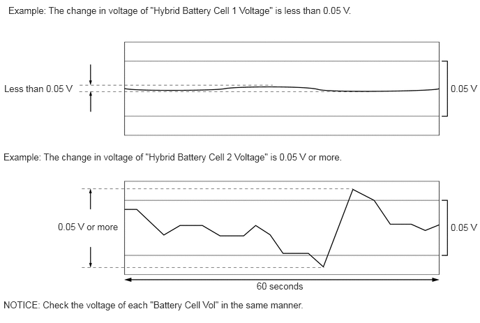
- Specified Condition:
Any "Hybrid Battery Cell Voltage" changes by 0.05 V or more, 60 seconds after the power switch is turned on (IG). (The difference between the maximum and minimum voltage is 0.05 V or more.)
- Result:
Result Proceed to The change in voltage of any "Hybrid Battery Cell Voltage" is 0.05 V or more. A Other than above B
Turn the power switch off.
A
B