2ZR-FXE ENGINE CONTROL AIR FUEL RATIO SENSOR REMOVAL
CAUTION / NOTICE / HINT
The necessary procedures (adjustment, calibration, initialization or registration) that must be performed after parts are removed and installed, or replaced during air fuel ratio sensor removal/installation are shown below.
| Replaced Part or Performed Procedure | Necessary Procedure | Effect/Inoperative Function when Necessary Procedure not Performed | Link |
|---|---|---|---|
for 2ZR-FXE
·
Replacement of air fuel ratio sensor ·
Gas leak from exhaust system is repaired |
Inspection After Repair | ·
Poor idle, etc. ·
Engine start function, etc. |
( ) |
- CAUTION:
- ·
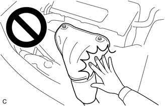
When the engine is hot, do not touch high-temperature areas such as the engine or exhaust manifold.
·Touching high-temperature areas such as the engine and exhaust manifold could result in burns.
PROCEDURE

 1.REMOVE WINDSHIELD WIPER MOTOR AND LINK ASSEMBLY
55737B
2.REMOVE NO. 1 HEATER AIR DUCT SPLASH SHIELD SEAL
55735A
3.REMOVE WATER GUARD PLATE LH (for TMC Made RHD)
55736D
4.REMOVE COWL BODY MOUNTING REINFORCEMENT LH
55735C
5.REMOVE COWL BODY MOUNTING REINFORCEMENT RH
55701J
6.REMOVE OUTER COWL TOP PANEL SUB-ASSEMBLY (for LHD)
55701J
7.REMOVE OUTER COWL TOP PANEL SUB-ASSEMBLY (for RHD)
89467B
8.REMOVE AIR FUEL RATIO SENSOR
- CAUTION:
- ·
When the engine is hot, do not touch high-temperature areas such as the engine or exhaust manifold.
·Touching high-temperature areas such as the engine and exhaust manifold could result in burns.
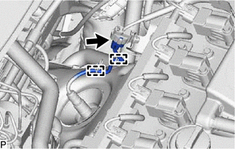
Disconnect the air fuel ratio sensor connector.
Disengage the 2 wire harness clamps.
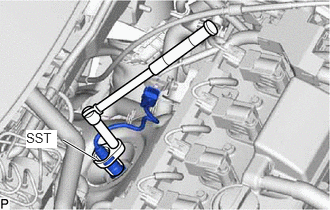
Using SST, remove the air fuel ratio sensor from the exhaust manifold (TWC: Front Catalyst).
- SST
- 09224-00012
- NOTICE:
-
If the air fuel ratio sensor has been struck or dropped, replace it.